


Introduction
An externalized transapical guidewire (ETAG) technique has been used for safe delivery of high-profile devices through a tortuous aorta to zone 0 in the case of endovascular treatment of aortic arch pathology. The ETAG technique is currently precluded after mechanical artificial aortic valve replacement (AVR). This is the first presentation worldwide of this newly discovered technique.
Aim
The aim of the study was to present a newly discovered modification of the ETAG technique which was successfully used in three cases qualified for endovascular full aortic arch repair after the Bentall procedure with a mechanical artificial aortic valve.
Material and methods
Patient
This is a report of one center’s experience regarding a newly discovered modification of the ETAG technique. We present one of the cases, thought to be most representative in general for this technique. A 67-year-old woman with complicated (rupture and cardiac arrest) type A aortic dissection had undergone emergency open surgery of the ascending aorta with implantation of an artificial aortic valve and ascending aorta conduit (Masters HP Valved Graft with Gelweave Valsalva Technology, Abbott Vascular 3200 Lakeside Drive, Santa Clara, CA, USA) and coronary arteries transplantation (Bentall procedure). This conduit contains a St. Jude Medical Heart Valve (a double-disc artificial valve). Unfortunately, 2 weeks after the operation, computed tomography (CT) revealed a pseudoaneurysm with a large hematoma covering a suture line defect (Photo 1).
Photo 1
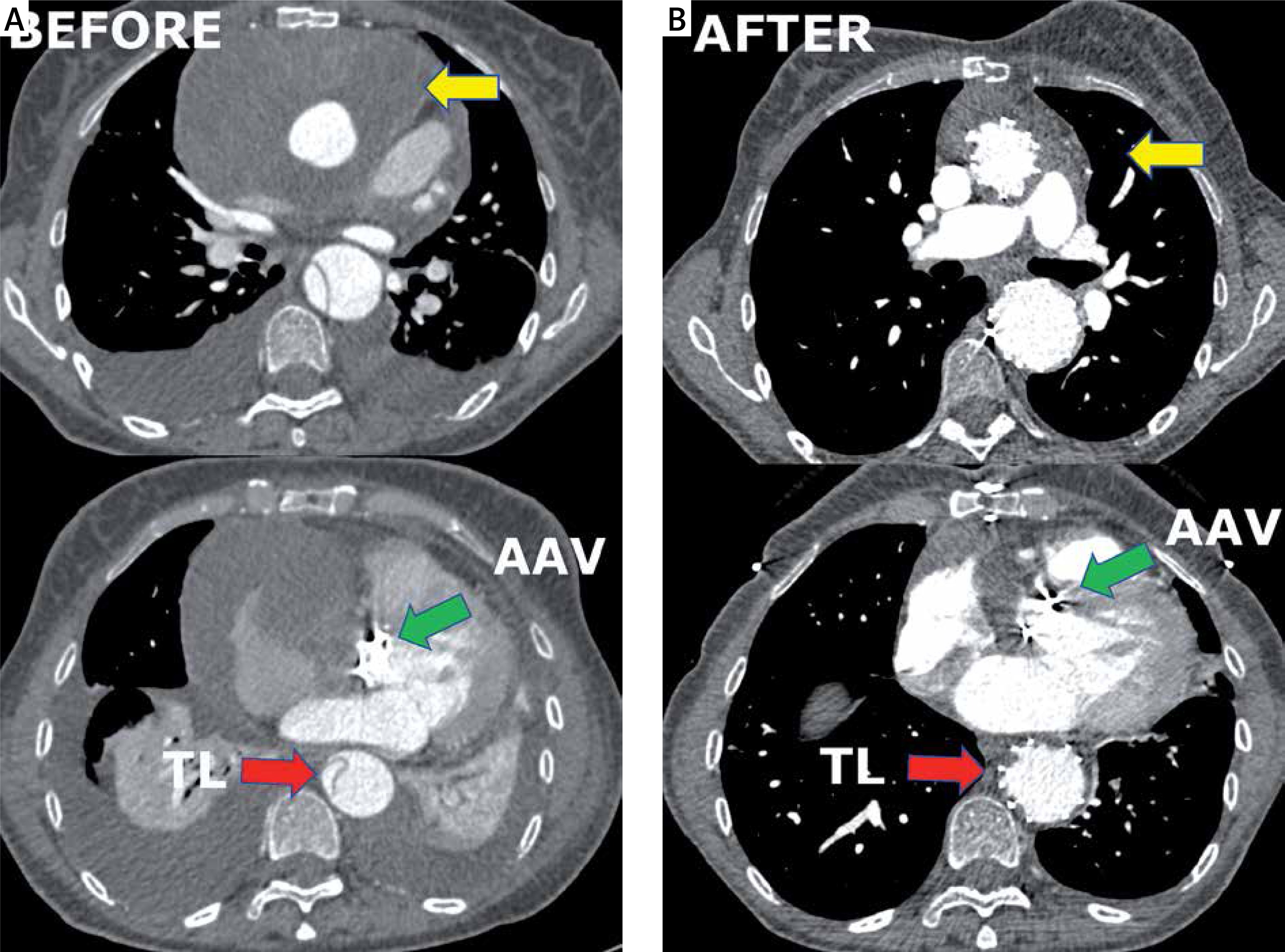
Computed tomography angiography imaging. A – Before. Green arrow indicates the position of the artificial aortic valve. Yellow arrows show a hematoma and pseudoaneurysm in the ascending aorta. Red arrow indicates the collapsed true lumen. B – After. Green arrow indicates the position of the artificial aortic valve. Yellow arrows show the shrunken hematoma in the ascending aorta. Red arrow indicates the fully expanded true lumen
The patient required urgent treatment. The risk of a second open procedure 3 weeks after the first operation was high (logistic EuroSCORE = 47.96%) and technically difficult due to an unfavorable anatomic condition (with arch angulation 90° backwards). The patient was unsuitable for any market-available arch devices.
Surgical technique
As a last resort we qualified her for endovascular treatment with a physician-modified endograft planned with a 3D print template (PMEG-3D). Due to the presence of a bovine arch (with common origin of the innominate artery and left common carotid artery) we planned the stent graft with only two fenestrations (to the innominate and left subclavian artery). Additionally, closure of the left common carotid artery (LCCA) and bypass to the left subclavian artery (LSA) were necessary (Photo 2 D).
Photo 2
Bench test and graft modification. A – Sharp angulation of the ascending aorta after previous surgery. Blue arrow shows the direction of the tip of the stent graft towards the pseudoaneurysm. B – Mobility (red arrow) of the soft Terumo guidewire inside the ring of the artificial aortic valve. C – Steering of the position of the wire by the 12 F vascular port (working as a lever – red arrow) from the apex (working as the fulcrum of the lever – blue arrows). D – Schedule for the procedure. E – Stent graft modification (blue arrow shows the position of the left subclavian artery (LSA) fenestration, red arrows indicate double longitudinal ties). F – Further stent graft modification with pre-cannulation of the LSA fenestration (yellow arrow), shortening of the tip of the introduction system (green arrow), position of the LSA fenestration (blue arrow)
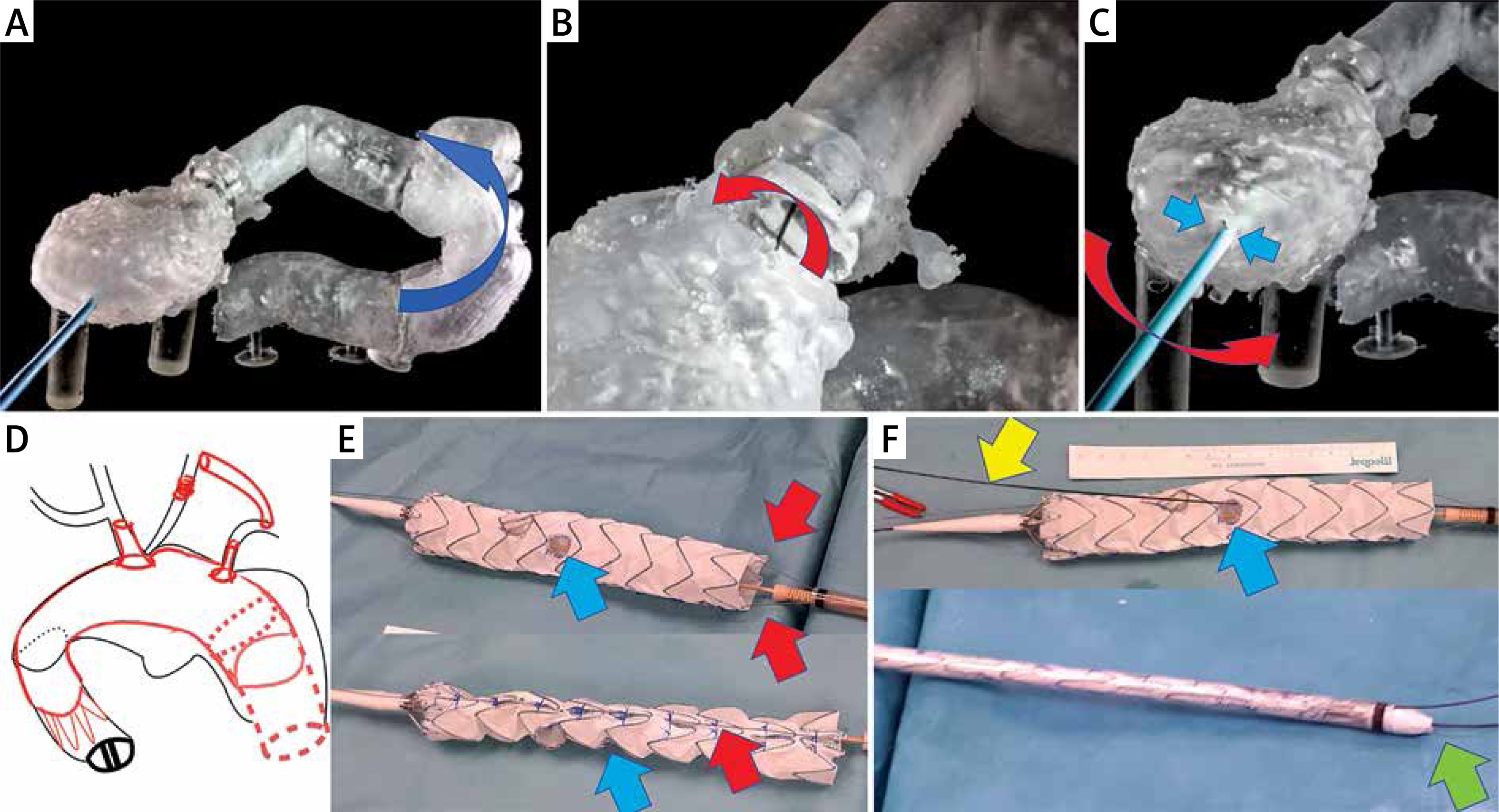
Unfortunately, due to the sharp angulation of the arch after previous surgery, it was impossible to insert the stent graft without the risk of aortic rupture. The presence of hematoma and pseudoaneurysms in distal anastomosis of the Bentall repair carries a certain risk of detaching the arch from the prosthesis. Every attempt to push the stent graft into the aortic arch in the 3D model, even after the introduction of a super-stiff guidewire, bent the guidewire and led the tip of the stent graft directly into a pseudoaneurysm (Photo 2 A). The ETAG technique was demanded, but impossible according to current guidelines.
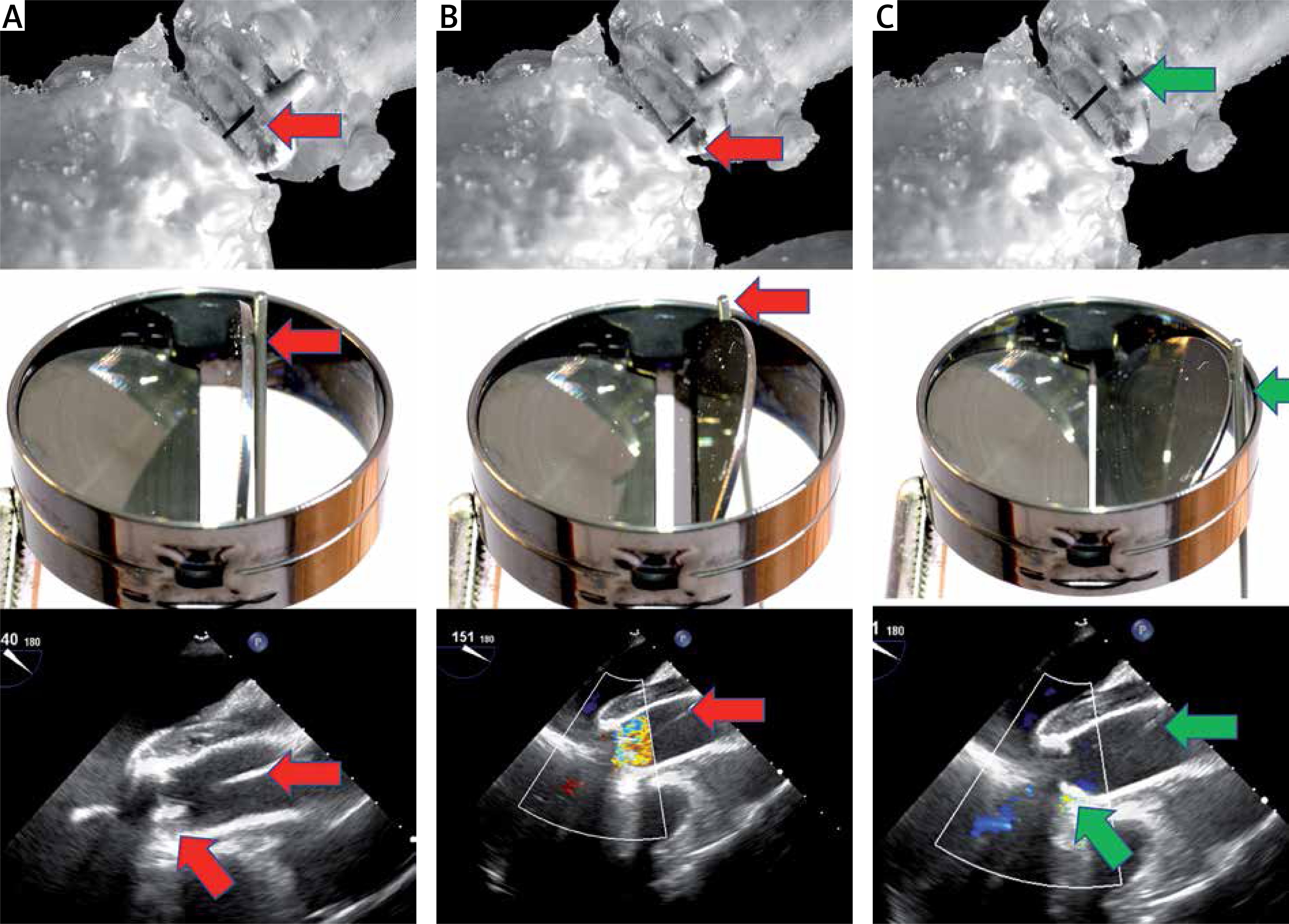
Despite this, an attempt was made to simulate the behavior of the artificial heart-valve discs at different positions as the guide passed through the mechanical valve. It transpired that keeping the guidewire away from the hinges of the valve and its center enabled maintenance of the proper function of the discs (it did not block the disc) (Photos 2, 3).
Photo 3
Guidewire position in the ring of the artificial aortic valve and the function of the valve. A – Guidewire (red arrow) in the center of the incompetent valve (valve blockade). B – Guidewire (red arrow) close to the hinge of the valve (incompetent valve function). C – Optimal position of the guidewire (green arrow) in the valve ring (competent valve)
For this purpose, a 3D model was created that included the ventricle, aortic valve and the entire ascending aorta, arch and the descending aorta, that allowed a simulation which involved changing the position of the guidewire in the artificial valve ring (Photos 2 B, C). It appeared possible to control the position of the soft guidewire (0.36 mm/0.014-inch Terumo, Europe, Interleuvenlaan 40 3001 Leuven, Belgium) from the apex using the 11 F vascular port (Photo 2 C). The guide could be freely positioned in the valve ring by means of a lever whose arm was a rigid vascular port inserted into the chamber through the apex. The fulcrum of the lever was the apex of the heart (Photos 2 B, C). This technique was used during the procedure. For this purpose, one of the surgeons constantly corrected the position of the guide in the valve ring based on the transesophageal echocardiography image.
Access to the apex was performed from a mini-thoracotomy via the 4th intercostal left space. Access to the common femoral artery for stent graft insertion was through the right inguinal region. The left femoral artery was punctured to introduce a pigtail diagnostic catheter into the arch. The right subclavian artery was exposed for temporary connection of a 14/7 mm bifurcated prosthesis (Maquet knitted double velour vascular graft, USA). One of the arms of the prosthesis served as a working channel for cannulation of the fenestration in the stent graft. The second arm of the prosthesis was blinded and provided a rescue route for the connection of extracorporeal circulation in case of valve blockage, heart dilatation and cardiac arrest. The left axillary artery was used for the LSA fenestration. Before the endovascular part of the operation was performed, a carotid-subclavian bypass was made using a 6 mm PTFE prosthesis (Gore, CA, USA) and a proximal section of the left common carotid artery was tied up. This was necessary because triple fenestration of the stent graft, due to a bovine arch, could not be performed.
Thoracic Valiant Captivia stent grafts (Medtronic, Santa Rosa, CA, USA/size: VAMF3636C200TE) were released in a sterilized aortic arch model and after optimal positioning of the metal frame the IA and LSA departure points were marked. Then the holes for the IA and LSA were burned. Their edges were lined with the wire cut out from the snare, strengthening the fenestration edge and marking the holes. A double lateral (longitudinal) tie made of two V-18 Control Wire Guidewires (Boston Scientific, USA) was used to optimize the rotation of the systems when inserting them into the aortic arch (Photo 2 E) [1]. The idea was that the planned holes should be opposite the external curvature of the curve of the aortic arch, both when inserting the delivery system into the curve and after the partial opening of the stent graft. Partial opening of the stent graft and traction towards the minor curvature (using ETAG) were necessary to leave space for the cannulation of fenestrations from the side of the larger aortic arch curvature to reduce the risk of stroke due to embolism, with material release from the external arch curve. Moreover, the stent graft tip was shortened by 1.5 cm to land as close to the mechanical valve as possible (to extend the proximal landing zone) (Photo 2 F). In addition, fenestration for the LSA was pre-cannulated. This means that a 0.36 mm (0.014 inch) soft Terumo guidewire was fed through the delivery system, inserted from the bottom into the stent graft and fed through the LSA hole (Photo 2 F) [2]. Then, before inserting the stent graft, the LSA pre-cannulation guidewire was first pulled from the right groin into the left armpit. Preliminary LSA cannulation was performed because it allows better arch navigation (it is easier to determine whether the graft is rotated and at which angle) and accelerates hole cannulation (to insert the 8 F and 45 cm long vascular port into the fenestration cut in the stent graft). The stent graft was packed avoiding rotation into the delivery system.
First, a guide from the right groin to the left armpit was deployed (with externalization of the LSA pre-cannulation wire). The stent graft was then introduced through the same groin into the ascending aorta and arch using ETAG with a 0.36 mm soft Terumo guidewire introduced from the apex to the right groin under the control of transesophageal echocardiography (TEE) and X-ray.
The position of the guide in the valve ring was constantly controlled by one of the team members dedicated only to this function (this is our unique, a newly discovered modification of the ETAG technique – technical note). It was necessary to keep the guidewire at the valve ring in a position that would allow the disc to close. A change in position towards the center of the valve or sideways (too close to one of the disc hinges) resulted in its blockage, severe regurgitation leading to dilatation of the chamber and bradycardia. A rapid response with change in positioning of the guide restored good mobility of the disc and reduced regurgitation. This technique allowed maintenance of stable circulation throughout the procedure (Photo 3).
Prior to stent graft release, rotation and positioning of the left subclavian artery (LSA) and innominate artery (IA) estuaries were checked by arteriography via a pigtail catheter inserted through a puncture from the left groin. The stent graft was then released from the shirt (it remained partially relaxed due to two lateral ties). Both fenestrations were cannulated. Catheters and then covered stents were placed: 16 × 38 mm B-Graft stent (Bentley InnoMed GmbH, Lotzencker 25, 72379 Hechingen, Germany) was placed in the IA and an 12 × 29 mm Advanta stent (Getinge, 40 Continental Blvd, Merrimack, NH 03054, USA) in the hole in the LSA fenestration. Then both lateral ties were released and another stent graft was implanted into the descending aorta (Medtronic Vailant Captiva, VAMC4036C150TE) below the LSA fenestration. This was done as a preparation of the landing zone for further procedures in the thoracic and thoracic-abdominal aorta in the future. A Tri-lobe balloon (Gore, Flagstaff, Arizona, 86003-2400 USA) was used to expand the stent grafts and their connections over the entire length, except for the last segment of the distal stent, to avoid aortic rupture or stent-induced new entry (SINE) [3]. Afterwards the guide was removed from the ventricle and valve. After this, it was not necessary to continuously monitor the aortic valve function with TEE. The covered stents in the fenestration holes were released in the IA and LSA and their intra-aortic sections (5–8 mm protruding into the stent graft body) were flared by balloons 2 mm wider than the IA and LSA stents. Arteriography confirmed the patency of the arch vessels and the lack of leakage to the false lumen. The delivery system was removed and the access vessels closed up.
Results
As a result, the course after the procedure was not complicated. The patient was discharged 10 days after the second procedure with CTA control after 2 months and good graft function with no leakage. There was a clotted false lumen in the arch. No SINE below the thoracic stent graft was seen (Photo 4).

CTA revealed persistent flow in the false lumen below the thoracic stent graft, a shrunken hematoma around the prosthesis, a reduced volume of the false lumen below the graft and better perfusion of the true lumen in the visceral segment of the aorta (Photo 1 A).
All of our 3 patients are now in follow-up and will receive life-long computed tomography angiography every 6 to 12 months.
Discussion
The need for ETAG might be greater than previously thought, because many patients have received open repair of the ascending aorta due to type A aortic dissection, but despite initial success, after some time have developed aneurysms in the aortic arch. Most of these initially had received a mechanical artificial aortic valve. In many of these cases market-available devices might not be suitable or available in emergency conditions, and until now mechanical aortic valves have given contraindication to ETAG [4].
ETAG is used when it is necessary to pull the graft into the arch [5, 6]. In urgent cases, when (1) open surgery is contraindicated and custom-made inner branch devices are not available or (2) these devices cannot be implanted into the arch due to an artificial aortic valve or lack of suitable landing zone (e.g. by Arch Branch Endovascular Graft from Cook Medical, Brisbane, Australia), the procedure described using PMEG is feasible [7, 8]. Such grafts could be planned on the basis of computed tomography angiography (CTA), and use of a 3D printing template ensures optimal graft modification [9, 10]. The 3D model also helps to predict problems with the introduction of the delivery system to the arch and the ascending aorta [10]. In some cases (e.g. in the present case) the ETAG technique appears to be the best solution to overcome difficult aortic anatomical configurations (in this case the sharp angle of the arch and pseudoaneurysm directly in the way of the stent graft tip). This helps to achieve an optimal landing zone in zone 0 by parking the delivery system as close to the aortic valve as possible. This also allows minimization of the stroke risk by keeping the delivery system away from the external aortic curvature [5]. Most importantly, the rigid vascular port used as a lever, inserted through the apex (fulcrum), allows avoidance of disc blockade. In this way the guidewire is actively controlled during the ETAG and quickly overcomes possible rapid artificial aortic valve incompetence.
Until now a mechanical valve has been an absolute contraindication for this type of technique, because the blockade of only one of the discs promptly leads to severe acute over-congestion of the left ventricle. Therefore, the length of time for the transvalvular approach should not exceed 5 min. This is recommended during percutaneous procedures closing paravalvular leaks in the mitral valve in cases which already have an artificial aortic valve (when the delivery system is passed through the femoral artery, through the artificial aortic valve up to the mitral valve) [11, 12]. For arch TEVAR the time taken to keep the wire within the aortic valve usually exceeded 60 min because time is needed for advancing the delivery system, positioning it in the arch and cannulation of the fenestration after its partial release before the transapical wire can be removed.
Nevertheless, active wire control supported by TEE makes this possible [13]. The TEE helps not only with positioning the wire in the ring of the artificial valve (controlling the valve movement, regurgitation and disc position), but also allows assessment of heart chamber function (checking preload and over-congestion). An additional important issue, based on our experience, is the choice of guidewire. We have noticed that the only types that can be used for ETAG with mechanical valves are soft [14]. Stiff wires such as Back-up Meier (Boston Scientific), Lundrequist or Amplatz Support Wire (Cook Medical) used in standard TEVAR procedures are contraindicated because these block the disc and may rip it or damage the surface of the ring. These complications are not an issue in the case of soft hydrophilic wires. A soft wire allows easy control of its position from the apex (lever/fulcrum), to slip nicely on the surface of the disk and ring, which reduces the risk of damage.
This case is the first successful attempt to use the ETAG technique in a patient with a mechanical aortic valve. So far, we have successfully used our modified ETAG technique in three similar cases.
The presented new technique has some limitations. This report has only proven that it is possible to carry out the ETAG procedure effectively after mechanical AVR in these cases. Therefore, we will collect data from a case series in future. As the hinges of the mechanical valve are positioned freely in relation to the axis of curvature of the aortic arch, we recommend performing a bench test to the check the ability to control the guidewire in a 3D model in every case in advance. It is also necessary for the surgeon controlling the position of the guidewire in the valve ring to have a good understanding of TEE images. Segmentation of the chamber and valve during the preparation of the 3D model requires high quality CTA guided by ECG. Additionally, coronary artery status must be checked before the procedure to avoid complications related to coronary artery spasm during apex manipulation. Therefore, a multidisciplinary team is needed during implantation and should include a vascular surgeon, cardiac surgeon and interventional cardiologist.