
Purpose
Brachytherapy (BT), especially high-dose-rate (HDR) BT, is an important part of modern treatment approaches in radiotherapy. In particular, the possibility of delivering a highly conformal dose distribution on a limited area with high-dose gradient is often used to spare critical structures.
One of the important developments in BT in recent years has been the clinical implementation of complex modern technical procedures for basic treatment concepts. 3D imaging has become the standard procedure, and it is used for contouring and precise position determination as well as reconstruction of used applicators. Treatment planning is performed on the basis of these imaging methods, followed by the transfer of treatment planning data to the afterloading device. Furthermore, model-based dose calculation algorithms (MBDCAs), e.g., using a deterministic solution of the linear Boltzmann transport equation, are available in BT [1]. Despite the fact that BT is a safe treatment method, errors can occur [2,3], especially because BT systems are increasing in complexity. Failures during the applicator reconstruction [4] within the treatment planning system (TPS), based on computed tomography (CT) imaging, have not been detected by using conventional radiographic film checks [5]. Through implementation of MBDCAs and the use of applicators libraries within the TPS, failures caused by imaging errors, misinterpretations, and data processing should be avoided. Therefore, checking the whole treatment planning chain becomes increasingly important for BT procedures. Besides periodical checks, commissioning tests after installation of a new system or system updates should be performed. In accordance with the recommendation of the German radiation-protection-commission [6], an end-to-end test procedure for CT-based BT using an HDR afterloading device is described in this study. In contrast to other system test procedures already published [7,8,9,10,11,12,13,14,15], the presented end-to-end test allows a check of the entire treatment planning chain, including the imaging system. The described system is easy to handle [16], given its compact size. Testing of imaging, applicator reconstruction, data transfer, source strength, dose calculation, and treatment delivery becomes available for clinical routine, with presented procedure.
Material and methods
Use of end-to-end test
The treatment planning chain of this study consisted of a SOMATOM S64 single-energy CT scanner by Siemens Medical (Erlangen, Germany), the TPS BrachyVision v.13.7 by Varian Medical Systems (Palo Alto, CA), which utilizes the calculation formalism TG-43 and the MBDCA Acuros v.1.5.0 (Varian Medical Systems) as well as a GammaMedplus HDR afterloader (Varian Medical Systems) using a nominal 40.700 U (1 U = 1 mGy∙m2∙h-1) Ir-192 source, and a variety of applicators (steel implant needle, vaginal cylinder, shielded vaginal cylinder). First, several measurement setups for common applicators used in BT were developed with PMMA (polymethyl methacrylate) jigs for a water phantom (40 cm × 40 cm × 40 cm). These setups were CT scanned using a slice thickness of 0.085 cm, and the data was imported into the TPS. In the TPS, applicators were either reconstructed manually or, if available, imported using applicator library of the TPS. Test plans were then computed in the TPS. Finally, such calculated dose points were compared against measured dose points using a PinPoint 3D chamber (type 31016) of PTW Freiburg (Germany).
The phantom
One aim of this study was the development of a tissue-equivalent phantom, allowing a suitable procedure for reviewing the treatment planning chain, and using it for consistency checks of CT-based HDR-BT in clinical routine. Accordingly, a water-based phantom with PMMA holders was designed. All dosimetric data were determined in the water phantom specially prepared for this work (Figure 1), which was partly (~7 cm above the measurement chamber) filled with water.
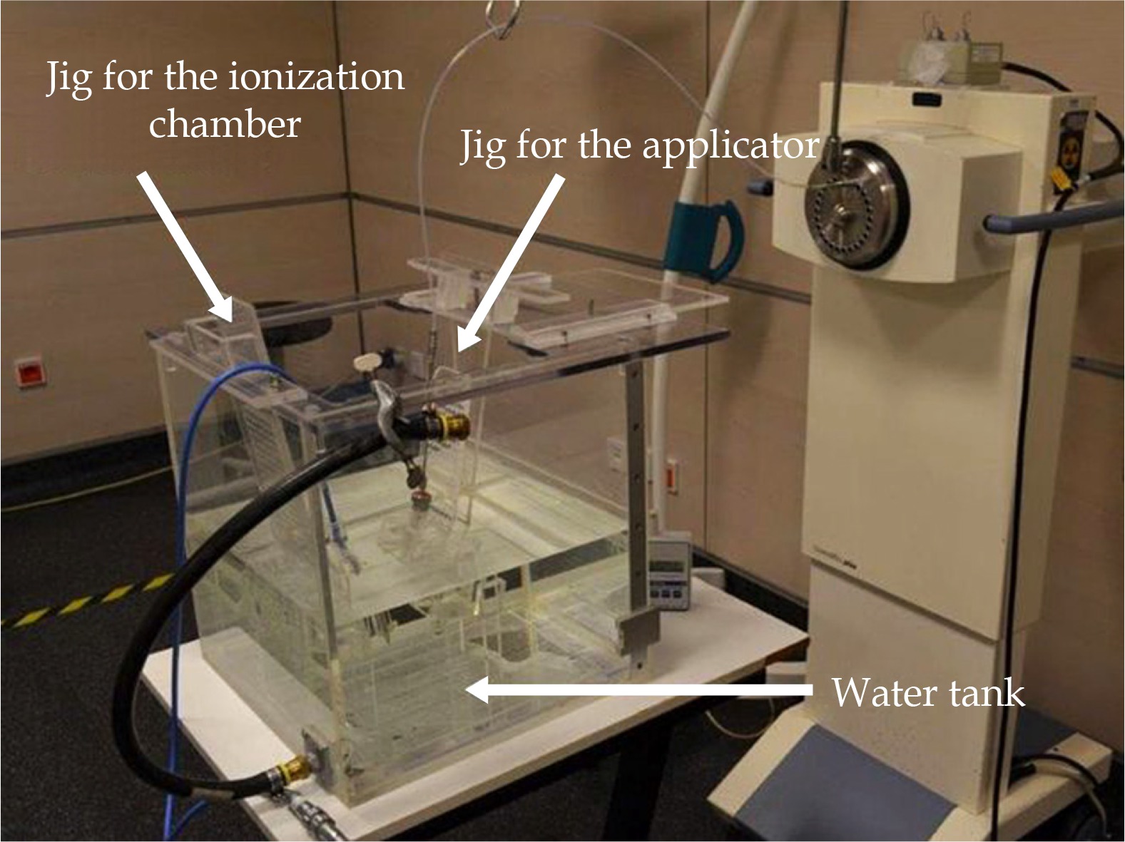
Applicator holders as well as measurement chamber holder were custom made PMMA jigs (Figures 2 and 3) mounted in the phantom tank. The PinPoint chamber and the respective applicator were fixed in the water tank at an isotropic distance of at least 7 cm from the phantom walls to approximate full scatter conditions. The phantom size was kept small because of handling issues. A distance of 7 cm was sufficient to ensure there are no significant (< 1%) dose reductions [17] due to lack of full scatter conditions. Thus, the total weight of the water-filled phantom could be limited to 30 kg. To reduce artifacts in the CT imaging, any screws required for fixation are manufactured from PMMA or nylon to have only nearly tissue equivalent materials in the phantom setup.
Fig. 2
Detailed view of the used PMMA fixation for the PinPoint 3D chamber as well as vaginal cylinder applicator
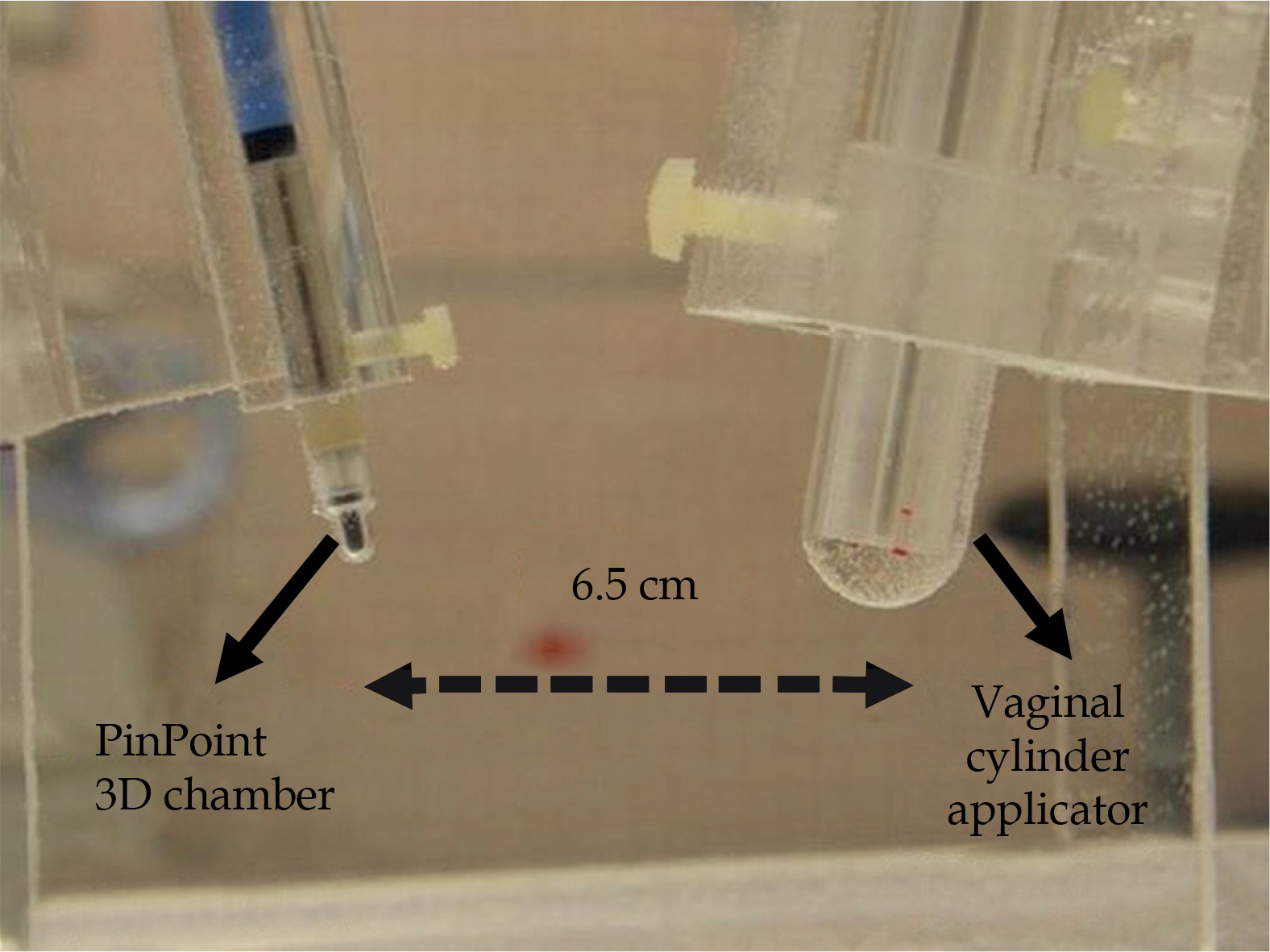
Fig. 3
Close-up sagittal view of the CT data of the used PMMA fixation for the PinPoint 3D chamber and the used unshielded vaginal cylinder (without inlay) taken from the CT scan after applicator reconstruction
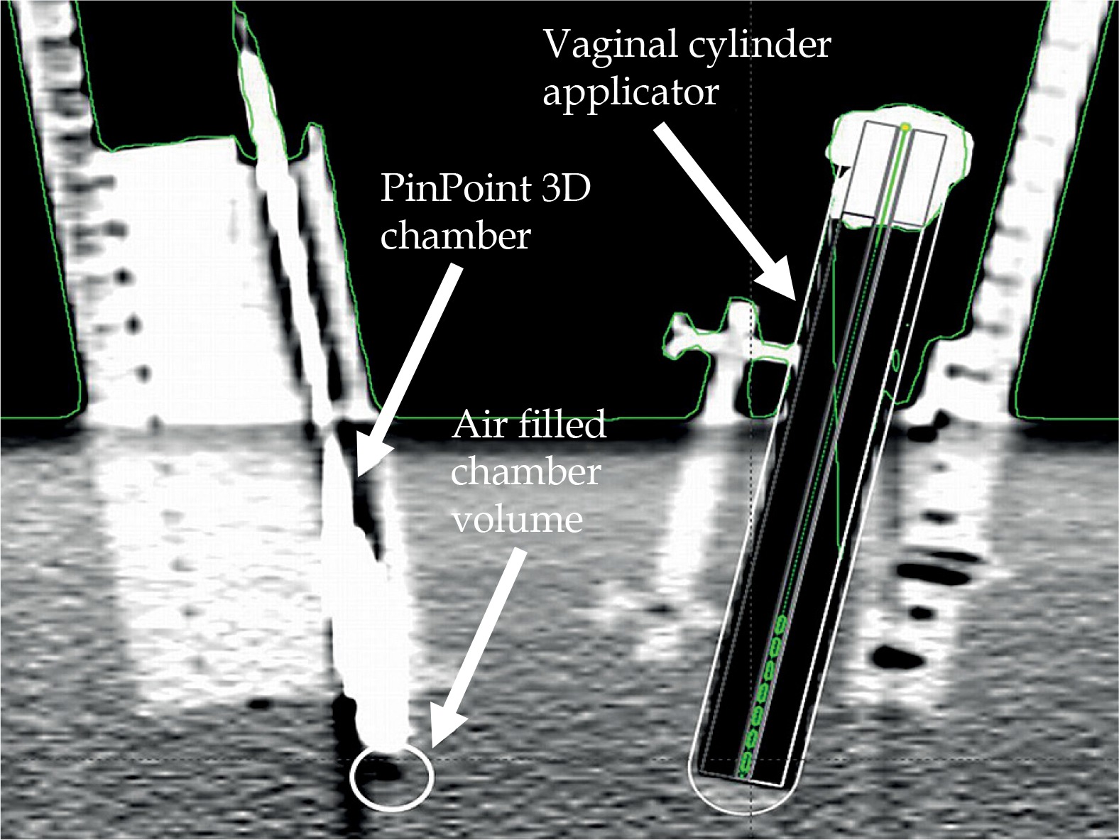
A vaginal cylinder applicator can be used in practice with partial shielding; therefore, some of the PMMA segments can be replaced by tungsten shielding segments to provide a variety of shielding coverage (90° and 180°). This study uses 180° shielding. The scan with the vaginal cylinder applicator was carried out without PMMA or tungsten inlay in order to avoid artefacts therefore, having better visibility of the cylinder applicator in the CT data set. For the applicator reconstruction, a template from the applicator library in the TPS was used, which included all geometry and density information of the used cylinder setting. Consequently, it was not necessary to perform a separate CT scan with the insert to acquire density information of the applicator.
Workflow
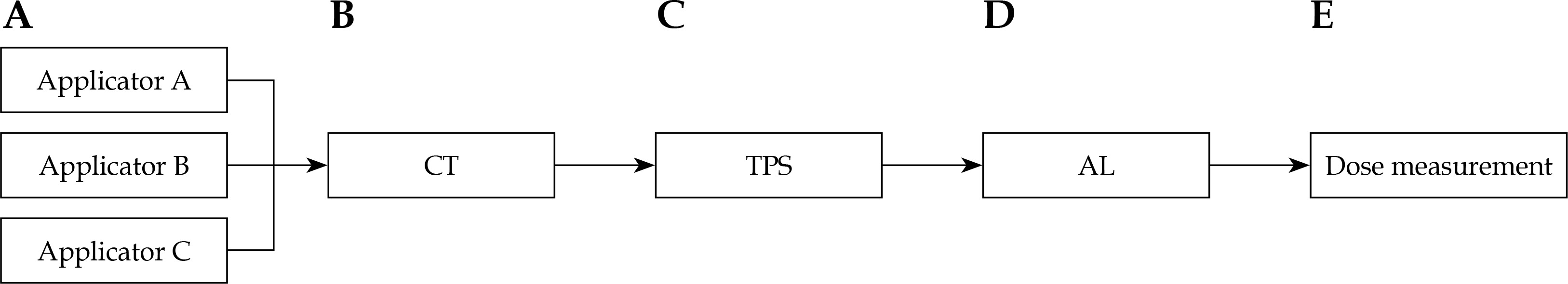
The presented procedure was used to review all planning instances in the treatment planning chain (Figure 4) containing the following components: CT scanner SOMATOM S64, the TPS BrachyVision (v. 13.7), and the afterloading device GammaMedplus. Computed dose values were calculated using the TG-43 formalism and the Acuros® calculation algorithm (Varian Medical Systems, Palo Alto, CA).
Measurement of dose to water Dw
All measurements using ionization chambers were performed with a 0.016 cm3 PinPoint 3D chamber 31016 of PTW (Freiburg, Germany). A high spatial resolution was achieved through the small, sensitive volume, which can be used for dose measurements in small photon fields of external beam radiotherapy and also in HDR-BT. Measurement of the dose to water was done according to the DIN 6800-2 [18] report (1):
where Dw is dose to water [Gy], M is the measuring signal, M0 is background signal, N is calibration factor for conversion to dose to water, kTp is correction factor for air density, and kQm is correction factor for radiation quality [19].
The radiation quality correction factor kQm was used with reference to Chofor et al. publication [19]. The factor was determined through a semiempirical method by Chofor et al. and for this research, it was summarized to an average value to match the self-made phantom in size as well as the energy of the iridium source. This was done because the phantom dimensions utilized lied within the phantom size range indicated by Chofor et al. For the PinPoint 3D chamber 31016 manufactured by PTW Freiburg, Germany, the correction factor amounts to kQm = 1.014 and corrects all experimentally collected data.
All measured values of the total accumulated dose given in the following sections, corresponded to the mean value of a measurement series consisting of five measurements. The uncertainty was given in standard deviations (k = 1).
Applicator–detector distance
Previous research [20] has shown that a distance of 6 cm to 8 cm between the applicator axis and the chamber center was suitable to obtain the largest possible measurement signal, while concurrently considering the steep dose gradient of the Ir-192 source. In this study, a distance of 6.5 cm from the center of the implant needle or unshielded cylinder (with a diameter of 2 cm) to the center of the ion chamber was chosen (Figure 5). A distance of 6 cm was chosen for the shielded cylinder applicator, considering the dose reduction behind the tungsten shielding.
Functionality
To verify the functionality of the measurement setup, measured point dose values were compared to the calculated doses. The phantom was sequentially tested with two different applicators: an implantation needle (IN) type K50 by Varian Medical Systems and an unshielded vaginal cylinder (VC) with a diameter of 2 cm, also by Varian Medical Systems. For both applicators, one dwell position of 60 s at the applicator’s most distal position (130 cm) of the afterloader was considered.
Resolution
To determine the spatial resolution of the phantom setup, the source holding position was gradually shifted in six 0.5 cm steps, starting from dwell position at 130 cm up to dwell position at 127.5 cm within the applicators (IN, VC). Measurements were done at each position. Spatial resolution of the system was evaluated, based on this data.
Reproducibility
Positioning reproducibility, while assembling and disassembling mechanical parts, was taken into consideration to check the mechanical stability of the phantom. The reproducibility of the measurement setup was investigated by using three reconstructions of the configuration. In order to do so, the measurement setup was demounted and subsequently mounted again in the phantom. The jigs were removed from the water tank and the tank was emptied. Subsequently, the jigs were remounted, and the phantom was refilled. Computed values were determined by means of the CT data set only once at the beginning. This means that only a single CT scan was conducted, and the data derived from it were also used for the rebuilding of the measurement setups. This was done to identify a deviation in the reconstruction of the measurement setup. The dwell position and dwell time considered in ‘functionality’ were the same as before.
Water level
Some measurements were repeated at higher fill level (~10 cm above the measurement chamber) and examined for deviations in the measured and calculated values to check whether the water fill a level of 7 cm above the measurement chamber was sufficient with regard to scatter conditions. Two single dose points placed laterally to the Ir-192 source for two single dwell positions of 60 s at 130 cm and 127.5 cm were considered by using an implantation needle.
Planning algorithms
The commissioning guideline for new modern planning algorithms for BT, just like MBDCAs, is demanding. Therefore, it is worth evaluating how the presented phantom could help medical physicists as a part of the commissioning process to verify differences between dose measurements and calculations. Hence, measurements of a shielded vaginal cylinder were performed behind a 180°-tungsten shielding in the water phantom to point out differences between the calculation formalism TG-43 and the MBDCA Acuros. A patient plan (Figure 6) was computed with both algorithms, and the calculated values were compared with each other as well as against measured values.
Simulation of errors
Three test plans are defined for the unshielded vaginal cylinder and measured in the phantom. Each plan contains three dwell positions but differs in the arrangement of dwell positions or in the arrangement of dwell times at similar position (Table 1). The total irradiation time was not changed. The dwell position at 130 cm was located at the distal end of the catheter. This was done to simulate errors caused due to displacement of the applicator (plan b) and to examine to what extent an exchange of the dwell positions can be detected by phantom measurements (plan c).
Results
Functionality
The dose deviation between computation and measurement was shown to be ≤ 5% at the investigated positions (Table 2), when using an implant needle or an unshielded vaginal cylinder for both TG-43 and Acuros computation. Only the dose values for the implantation needle calculated with Acuros showed a slightly higher deviation of 8.5%, which can be attributed to artefacts of the steel needle in the CT scan.
Resolution
Looking at the experimental results (Figures 7 and 8), it is evident that both applicators have similar characteristics. A shift in dwell positions of 5 mm or more can be dosimetrically discerned with the presented setup.


Reproducibility
Furthermore, it can be shown that the system test procedure developed here provides reproducible results, while repositioning the used measurement setup without performing a new CT scan (Tables 3 and 4), considering dose variations of less than 5% and the resulting small uncertainty of measurement series.
Water level
Experiments with regard to the effect of the water level of the phantom on the measured water energy dose showed no influence of a water level > 7 cm above the detector (Table 5). Even at measuring positions with lower water level, because of the vertical shift within the applicator mounted in the water tank (e.g., dwell position 127.5 cm), no dose difference was shown.
Table 5
Deviations of the measured and calculated values depending on the fill level of the water phantom, for two different fill levels
Planning algorithms
It is also possible, as presented here, to determine differences between various calculation methods (e.g., Acuros and TG-43 formalism). In the following, an example was given for a 180°-shielded vaginal cylinder with 2 cm diameter. As illustrated in Figure 9, the tungsten shielding of the shielded vaginal cylinder can be displayed by calculation with Acuros. In contrast to the isodose levels in Figure 9, in Figure 10, the isodose levels calculated with TG-43 formalism showed no influence of the tungsten shielding.

A comparison shows phantom measurements being in good accordance with the values calculated using Acuros (Table 6). Thus, the system test phantom seems to be suitable to verify the introduction of new techniques like MBDCAs as Acuros.
Simulation of errors
Considering the results of the measured test (plans a-c), a simulated 1 cm displacement of the detector (plan b) and simulated exchange of dwell positions (plan c) can be identified and measured with the designed phantom.
Due to the applicator–detector distance of 6.5 cm, the dose differences between the original plan a and the simulated switched positions in plan c at 1.1%, although low, were detectable. A simulated misplacement of 1 cm in plan b causes a measured dose deviation of 9.4% at the point of measurement (Table 7).
Uncertainty analysis
For better understanding of the overall uncertainty of the presented end-to-end test, uncertainties of each individual step of the system test were evaluated (Table 8). The first step is the CT-based applicator reconstruction in the TPS. A reconstruction uncertainty of 0.11 cm (dose effect 3.1%) for the implant needle and 0.07 cm (dose effect 2.5%) for the vaginal cylinder were found. The uncertainty for the dose calculation was assumed to be 2.6 % [21,22] and for the source strength – 1.5% [21]. Furthermore, a systematic error of 0.01 cm was estimated for the uncertainty of the dwell positions [22]. This resulted in a dose effect of 0.6% for the implant needle and 0.5% for the vaginal cylinder. The long-term stability of the ionization chamber used was given as 1%. The uncertainty of the measurement chamber position can be determined at 0.01 cm, which resulted in dose effects of 0.6% for the implant needle and 0.5% for the vaginal cylinder. By repeating the dose measurements five times, the uncertainty for the dose measurement process was determined at 0.8% (implant needle) and 0.9% (vaginal cylinder). Thus, an overall uncertainty of 4.6% for the implant needle and 4.2% for the vaginal cylinder was calculated using a simple quadrature sum of the individual procedures, as shown in Table 8. The results for the vaginal cylinder can be adapted for the shielded vaginal cylinder in the same way.
Table 8
Uncertainty budget for the implant needle and the unshielded vaginal cylinder used within the presented end-to-end test under normal operating conditions
Discussion
Several approaches to determine the accuracy of dwell positions and dwell times for HDR-BT have been published in the last 10 years. A wide variety of detectors such as film dosimetry [7], ion chamber array [8,9], luminescence dosimetry [10,11] as well as diode array [12,13] test procedures deliver higher accuracy regarding resolution of dwell positions and dwell times. However, none of these test procedures measures in water surrounding or is suitable for use as an end-to-end test for the whole treatment planning chain. Also, real-time dosimetry [23,24,25] is available for in vivo dosimetry in BT. Though real-time measurements can identify a variety of different error scenarios (e.g., applicator displacement, interchanged guide tubes during therapy) and are a good indicator for the stability of the system, they are not suitable to exactly locate where errors occur during image and data processing (such as during the image data transfer into the planning system). Furthermore, the equipment required is expensive and not widely available. There are few concepts published in the literature related to end-to-end tests in HDR-BT. The published studies either focus only on displacement effects [14], or while delivering more precise results with regard to the combined standard uncertainty (3.2%) [16], which due to the size and construction of the used phantoms are not suitable for periodic in-house test procedures to check the entire treatment planning chain in clinical practice. Another system check shown [15], based on a PMMA-phantom, provides a system check for the planning chain without inclusion of the imaging system. Hence, the presented system check procedure in our opinion bridges a gap, because it not only allows a check of the entire planning chain with a dosimetric verification in water medium, but by reason of its size, it is also easy to handle and more flexible for testing a variety of different applicators with the same phantom as in other published concepts. Although PMMA-based phantoms provide a fixed geometry [15], an advantage of the presented water phantom is the possibility of easy adaption for checking a variety of other applicators. Instead of drilling new channels within a PMMA block, only minor modification of the applicator jig is necessary. Furthermore, for measurements within a water filled phantom, no additional correction factor for PMMA has to be applied. Moreover, due to their composition, the homogeneity of commercial plastic phantom materials is not always reproducible [26]. Thus, possible failure through the use of a wrong conversion factor is avoided. Moreover, the phantom presented in this study can be developed at a low cost and from parts available in most clinics as standard equipment. The phantom in this study can also be used to complement the commissioning of MBDCAs according to the TG-186 report [1,20].
Conclusions
The system test procedure presented in this study provides a practice-oriented realization for checking the entire treatment planning chain for HDR afterloading technique and CT imaging. It seems feasible to perform periodic system tests as well as to control the introduction of new techniques with sufficient accuracy. The dosimetric errors for the measured dose according to the AAPM Task Group No. 138 and GEC-ESTRO report [21] for high energies (3% with k = 1) are for the applicator detector distance of 6 cm and 6.5 cm, respectively, clearly undercut (about 2% with k = 1). With regard to the uncertainties (IN 5%, VC 8%) to be adopted in HDR-BT, as published in the directives by the GEC-ESTRO and AAPM [22], a sufficient accuracy is achieved. Thus, it is possible to check several different error scenarios during the planning process (e.g., dose calculation, source positioning, applicator reconstruction, data transfer) while using this phantom. Furthermore, the phantom can be used to verify new clinical approaches such as new planning algorithms (e.g., as recommended in the TG-186 report [1]). As part of a periodic test procedure, it is also possible to use the phantom for constancy checks of the entire treatment planning chain in clinical practice. Analysis of the resulting measurement uncertainties has shown that an important uncertainty factor is the measuring system or rather the phantom itself. It has, therefore, to be further elaborated how far the constructional parts of the phantom can be improved, e.g., by a CNC machine for manufacturing critical parts or using a smaller detector (e.g., microDiamond type 60019 of PTW Freiburg, Germany).


