Introduction
Aneurysms involving the extracranial segment of the internal carotid artery (EICA) are rare, accounting for up to 4% of all peripheral arterial aneurysms, and are most commonly of atherosclerotic origin, with secondary causes including trauma, dissection, connective tissue diseases, infection, and inflammation [1–3]. The resultant hemodynamic disturbances promote embolization and vessel occlusion, leading to neurological deficits; untreated lesions carry reported stroke and mortality rates as high as 50% and 70%, respectively. Although surgical repair has long been the gold standard – representing 0.2–5% of all carotid interventions – endovascular treatment has become an accepted alternative, particularly for surgically inaccessible lesions [4–6], aided by advances in stent technology and patient-specific 3D-printed simulation. The greatest remaining challenge is managing aneurysms with complex geometry, often complicated by secondary vessel deformation, inflammatory changes, and fibrosis.
Case report
This case report describes the use of a new-generation CARESTO® heal Stent (Acandis GmbH, Pforzheim, Germany) in a 69-year-old female patient with recurrent transient ischemia of the right hemisphere due to an extracranial internal carotid artery aneurysm with a highly complex anatomical configuration. This particular stent is constructed from coated nitinol composite wires with a platinum core; its dense, single-layer mesh design confers flow-diverting properties, while its high flexibility facilitates navigation through tortuous vessels, making it suitable for treating aneurysms and dissections in challenging anatomical settings [7].
In this patient, computed tomography (CT) angiography revealed a 5.2 cm extracranial internal carotid artery aneurysm located behind the angle of the mandible, with double angulations and stenosis of the parent artery (Figure 1 A). The patient was initially considered eligible for endovascular treatment, but after analyzing the vascular course (a highly tortuous course of the internal carotid artery above the aneurysm), a covered stent was deemed unfeasible due to the excessive stiffness of its delivery system. Following thorough analysis, the patient was instead scheduled for treatment with a new-generation CARESTO® heal Stent – a flow-diverting stent with a highly flexible delivery system.
Figure 1
A – CT angiography of the right internal carotid artery showing a giant aneurysm with a diameter of up to 5.2 cm in a 69-year-old female patient. B – Silicone models of the lesion (with the lower part of the aneurysmal sac removed), showing the bends of the artery containing critical stenoses (arrows). Views from the front and back of the model. C – Angiography after successful implantation of the Caresto stent in the silicone model; the model was used to determine the treatment strategy for this lesion with very challenging anatomy. D – Angiography of the actual aneurysm; white arrows indicate bends and stenoses corresponding to those visible in the silicone model. E – Angiography after the introduction of 0.014” guidewires to the distal part of the cervical segment of the internal carotid artery and placement of a reperfusion catheter just distal to the aneurysmal sac. White arrows indicate the sites of critical stenoses, corresponding to the bends visible in (D). F – Successful navigation of the NeuroSlider delivery catheter to the middle part of the C1 segment of the internal carotid artery. The arrowhead indicates the tip of the reperfusion catheter; a 0.014” guidewire is also visible. G – Initial stage of stent deployment. The arrow indicates the proximal segment of the stent during release; the white arrowhead indicates the tip of the NeuroSlider delivery catheter, and the black arrowhead indicates the tip of the Sofia support catheter. H – Aneurysm and internal carotid artery after stent deployment (first stage of the procedure), showing visible inflow into the entire aneurysmal sac
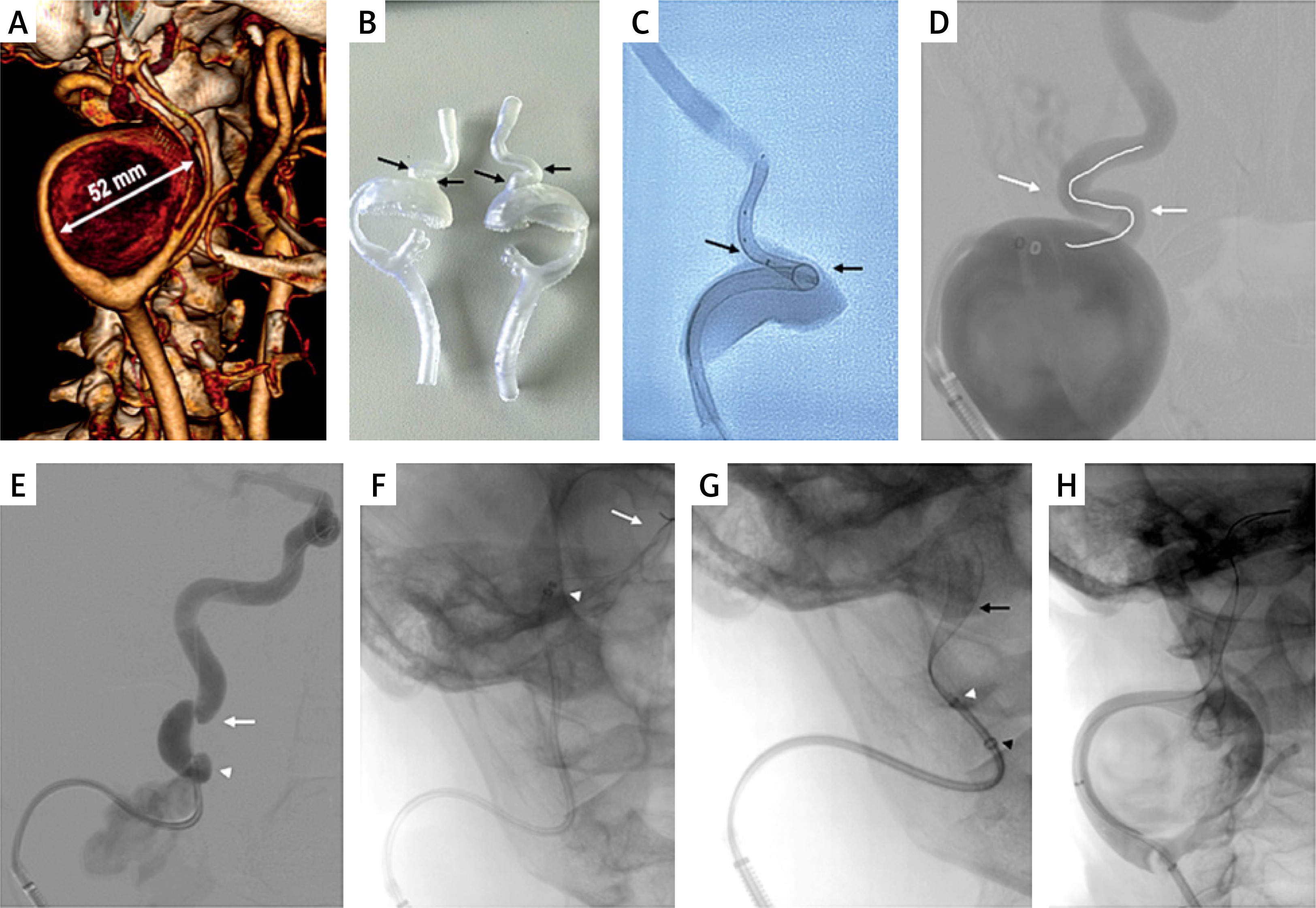
To determine the optimal treatment strategy, stent implantation procedures were performed under interventional radiology conditions using silicone models of the lesion (Figure 1 B). The models were prepared based on simulations derived from computed tomography data and produced using 3D printing technology with an appropriate type of silicone. Trial implantations confirmed that the aneurysm configuration (tortuosity and stenosis) represented a technically very challenging lesion, requiring supportive techniques (multiple guidewires, reperfusion catheters). The following endovascular treatment strategy was established:
Introduction of an introducer sheath into the proximal segment of the internal carotid artery,
With catheter support of an appropriate shape, introduction of two 0.014” guidewires, followed by advancement of the NeuroSlider delivery catheter, and then the stent,
Deployment of the stent within the aneurysm,
Repeated balloon angioplasty to achieve proper stent apposition to the vessel wall (it should be noted that full optimization cannot be achieved in the model, as the lesion does not expand in the silicone model).
The possibility of testing the delivery system and stent implantation in a silicone model proved to be very helpful and facilitated both preparation and the establishment of the procedural strategy (Figure 1 C). The patient was fully informed about the planned procedure, including the possibility of a multistage treatment approach, and informed consent was obtained.
The procedure was initiated by obtaining femoral access. A 6F, 90 cm sheath was introduced into the proximal segment of the internal carotid artery (Figure 1 D). Subsequently, with the support of an RBI 5F catheter (Merit Medical, South Jordan, USA), three 0.014-inch, 300 cm guidewires were gradually advanced into the distal segment of the internal carotid artery. However, after removal of the RBI catheter, attempts to advance 3.0 mm and 2.0 mm balloon catheters were unsuccessful due to looping of the guidewires within the aneurysm sac. Therefore, after removal of the balloon catheter, a Sofia 6F, 115 cm reperfusion catheter (MicroVention, Aliso Viejo, USA) was advanced over all three 0.014-inch guidewires into the proximal internal carotid artery, just above the aneurysm at the level of the first bend (Figure 1 E). In the next stage, a 3.0 mm balloon was successfully advanced into the internal carotid artery, and two inflations at 4–6 atm were performed at the level of the stenosis. The balloon was then positioned distally in the cervical (C1) segment of the internal carotid artery, and with the support of the guidewires and the balloon, the Sofia reperfusion catheter was advanced above the lesion into the distal portion of the C1 segment. In the following stage, after removal of two guidewires, a NeuroSlider delivery catheter (Acandis GmbH, Pforzheim, Germany) with a Acandis® Dilatator was advanced through the Sofia catheter using the telescopic technique over the remaining single 0.014-inch guidewire into the distal C1 segment (Figure 1 F). The guidewire and dilator were then removed. Next, the stent was introduced and slowly deployed (Figure 1 G). Control angiography revealed persistent kinking and critical stenosis of the internal carotid artery. Therefore, with support of two guidewires, the Sofia catheter was again advanced above the stent, and balloon angioplasty was performed sequentially using 3.0 mm, 4.0 mm, and 5.0 mm balloons, finally achieving a satisfactory result. Follow-up angiography demonstrated flow stagnation inside the aneurysm (Figure 1 H).
Considering the pioneering use of this type of stent in such a large aneurysm, it was decided to conclude this endovascular repair and perform follow-up evaluation after 3–4 weeks. In a subsequent angiographic examination performed after 4 weeks, stenosis of the stent was revealed at the level of the upper edge of the arterial bend, corresponding to the site of the initial most severe narrowing (Figure 2 A), and thrombosis of approximately 80% of the aneurysm volume (Figure 2 B). A 6F, 90 cm introducer sheath was again navigated into the mid-portion of the implanted stent, and a 6.0 mm Spider Fx embolic protection device (Medtronic, Minneapolis, USA) was advanced into the distal part of the C1 segment of the internal carotid artery. Intravascular ultrasound confirmed significant stenosis at the site of stent bending (Figure 2 B). Balloon angioplasty was performed at the site of stenosis using a 5.0×20 mm balloon (Figure 2 C), followed by implantation of an additional 6×30 mm RoadSaver stent (Terumo, Tokyo, Japan), yielding a good result on both angiography and intravascular ultrasound (Figure 2 D). After stent implantation, the maximum non-occluded portion of the aneurysm measured 29×19 mm (Figure 2 E).
Figure 2
A – Follow up angiography at 4 weeks shows bending and narrowing of the stent at the site of the initial critical stenosis. B – Follow-up angiography at 4 weeks shows approximately 80% thrombosis of the aneurysm, with persistent inflow into the space around the stent. Bending and narrowing of the stent at the site of the initial critical stenosis are visible (confirmed by IVUS). C – Balloon angioplasty at the site of the most critical stenoses (repeated several times). D – Final angiographic result after balloon angioplasty and RoadSaver stent implantation; IVUS confirmed good apposition of the stents to the arterial wall. E – Residual non-occluded portion of the aneurysm. F – 4-month follow-up angiography after balloon angioplasty and RoadSaver stent implantation shows full expansion of the stent but persistent contrast inflow into the space around the stent. The non-occluded part of the aneurysm measures up to 44 × 23 mm; IVUS shows good stent apposition in the distal segment of the stent. G – Positioning of a covered stent – previously implanted stents provided a framework that allowed for successful navigation and positioning of the final stent. H – Final result after implantation of the Viabahn covered stent (stent between the arrows). There is no inflow into the aneurysmal sac, and flow in the internal carotid artery and intracranial arteries is normal
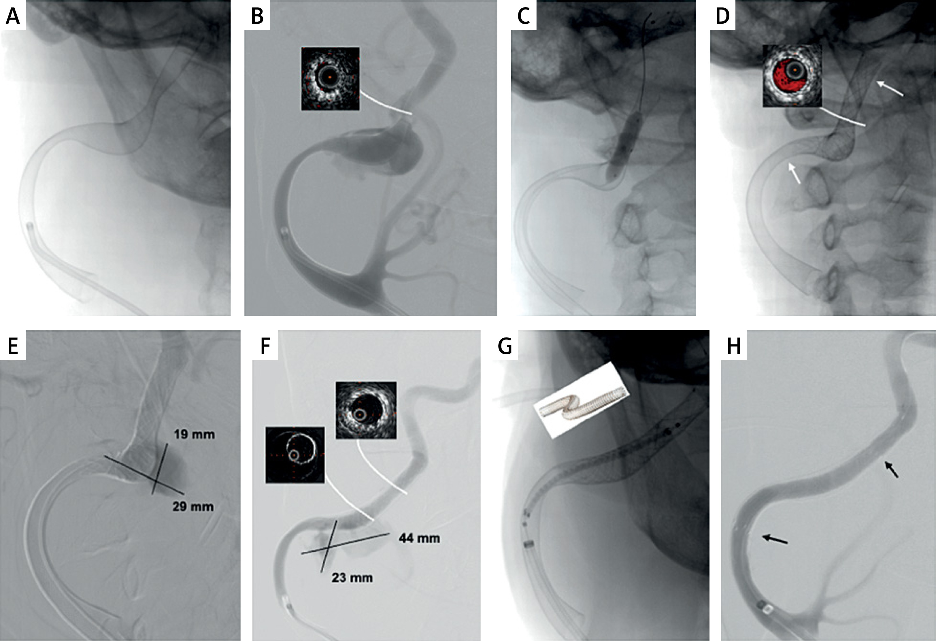
Follow-up angiography performed after 18 weeks demonstrated good stent apposition to the vessel wall, yet with persistent inflow into approximately 25% of the aneurysm sac in the region adjacent to the stent. The non-occluded part of the aneurysm had increased in size compared to the previous procedure and now measured 44×23 mm (Figure 2 F). Intravascular ultrasound demonstrated good apposition of the stents to the arterial wall above the aneurysm, with no visible vascular structures in the region of persistent inflow into the aneurysm lumen. This suggested a lack of therapeutic effect of the flow-diverting stent. It is possible that the area covered by the CARESTO® heal Stent was too large to achieve an adequate flow-diverting effect (Figure 2 F). Therefore, we decided upon stent-graft implantation to address the lesion.
Using a telescopic technique, a 6F, 90 cm sheath, a 6F, 115 cm reperfusion catheter, and a 125 cm 5F diagnostic catheter were introduced. With the support of a 0.014-inch guidewire, the 6F sheath was advanced into the C1 segment of the internal carotid artery. Subsequently (Figure 2 G), a Gore Viabahn 6 × 30 mm covered stent (Gore Medical, Flagstaff, USA) was introduced and implanted, followed by post-dilatation using a 5.0 × 20 mm balloon at 8–12 atm. The final angiographic result was good, with normal blood flow to the arteries of the right cerebral hemisphere (Figure 2 H). The post-procedural course at 6 months was uneventful, with no neurological symptoms. Ultrasound examination demonstrated complete exclusion of the lesion, with no inflow into the aneurysm lumen.
Discussion
A new-generation CARESTO® heal Stent, preceded by testing its deployment in a silicone model, allowed for the initial treatment of this very difficult angioarchitecture. This initial approach, however, required the subsequent implantation of an additional stent and, ultimately, a covered stent. The results of intraprocedural intravascular ultrasound suggested that this initial partial technical success was associated with the fact that the aneurysm was very large. Although the CARESTO® heal Stent was well apposed to the arterial walls in some parts of the aneurysm, there were still areas without arterial wall structures in proximity to the stent that would initiate the thrombosis process. Additionally, flow velocity in this area was likely too high to permit thrombus formation. Therefore, in this patient, the flow-diverting CARESTO® heal Stent primarily served the purpose of a scaffolding stent, which facilitated the final closure of the aneurysm by a covered stent.
It should be emphasized, however, that in the described case – apart from the use of a new-generation stent and a multi-stage endovascular treatment – the use of a silicone model of the lesion was a very important element that facilitated both the preparation and performance of the procedure. As noted above, stent implantation in the vascular laboratory revealed difficulties that might arise during the actual intervention. Indeed, the steps identified as particularly challenging during the procedure in the silicone model were confirmed to be equally challenging during real endovascular repair. Based on our own experience, we advocate the use of a silicone model for testing endovascular techniques in cases of anatomically challenging lesions. Such an approach facilitates the procedure and reduces the risk of potential complications. It should also be noted that an optimal simulation procedure should comprise all steps of endovascular repair, including stent implantation. However, in some cases, the cost of the stent may be prohibitive. Even so, it is still worthwhile to attempt to establish a strategy with less expensive endovascular devices in order to determine which catheters and guidewires (and techniques, such as the buddy wire technique) will successfully navigate across the lesion before stent deployment.
Conclusions
Despite the technical and clinical challenges, even extremely challenging aneurysms of the internal carotid artery have become amenable to endovascular management, although in some cases the repair may require multi-step procedures. Endovascular repair of these very challenging cases can be facilitated by simulation intervention in the vascular laboratory prior to the actual repair.