Introduction
During complex percutaneous coronary intervention (PCI), one of the biggest challenges is the inability to cross devices to the target lesions [1]. The buddy wire and anchoring balloon technique can be helpful in such situations [2, 3]. The mother-in-child technique is another powerful method [4, 5]. Applying a similar concept, the rapid-exchange guide extension catheter (GEC) has been evolving. Previous studies have proposed a mechanism of its efficacy as increasing back-up support by deep intubation, as a conduit to decrease friction between the vessel wall and the catheter, or for improving co-axial alignment between the catheter and the lesion [6, 7]. However, little is known regarding the differences in primary indication with respect to the target vessels.
Aim
The purpose of this study was to clarify the primary indication for GEC according to the target vessels and to provide thorough consideration of the mechanistic effect of GEC.
Material and methods
We enrolled 232 consecutive patients with 251 lesions (excluding left main and bypass-graft lesions) for whom GEC-facilitated PCI was performed between March 2014 and September 2018. Those who participated in another study were excluded [8]. The research review board of our hospital approved this study, which complied with the Helsinki Declaration. All patients provided consent for participation in this study.
GuideLiner V3 (Vascular Solutions Inc., Minneapolis, MN, USA), Guidezilla (Boston Scientific, Marlborough, Massachusetts, USA), or GuidePlus (Nipro Corp., Osaka, Japan) was used. The primary indication for GEC was defined as follows [6, 7]: 1) to increase back-up support; 2) as an outer sheath; 3) to facilitate co-axial alignment between the catheter and the lesion; 4) to selectively inject contrast; and 5) other. Although the complete differentiation among the indication of 1)–3), especially between 1) and 2), was hard to achieve, we defined the indication of 1)–3) as follows: the indication of 1) was defined in cases where the operators simply would like to increase backup support of a guiding catheter to facilitate delivering stents or a balloon with little awareness of the tortuosity or angle of the vessel proximal to the target lesion; indication of 2) was defined in cases where the GECs have passed beyond the lesions and the devices were delivered; indication of 3) was defined in cases where the tortuosity or acute bending proximal to the target lesions might underlie the difficulty to deliver devices (especially, short monorail with floppy shaft, such as intravascular ultrasound). Two experienced operators (R.Y. and K.T.) independently reviewed angiography and decided the primary indication. Any discrepancies between the two operators were resolved by consensus after consulting a third operator (Y.M.). Procedural success was defined as < 20% residual stenosis with thrombolysis in myocardial infarction 3 flow in the target vessel, and device success was defined as delivering GEC to the desired position. Tortuosity was defined as proximal segment angulation of > 90° and calcification was visually assessed [7].
Results
The mean age of the patients was 73.3 ±10.2 years and three-quarters of patients were men. Approximately one-half of the patients had diabetes mellitus, chronic kidney disease, or prior history of PCI. Angiographic and procedural characteristics are presented in the Table I. Calcified lesions were more frequent in the right coronary artery (RCA) and left anterior descending (LAD) artery than in the left circumflex artery (LCX), which resulted in more frequent use of rotational atherectomy in the RCA and LAD. On the other hand, proximal tortuosity was more frequent in the LCX.
Table I
Angiographic and procedural characteristics according to the target vessels
| Lesion characteristics | Right coronary artery n = 124 lesions | Left anterior descending artery n = 80 lesions | Left circumflex artery n = 47 lesions | P-value |
|---|---|---|---|---|
| Clinical indication for PCI: | 0.10 | |||
| Stable angina/silent ischemia | 88 (71.0%) | 61 (76.3%) | 35 (74.5%) | |
| NSTE-ACS | 15 (12.1%) | 11 (13.8%) | 10 (21.3%) | |
| STEMI | 21 (16.9%) | 8 (10.0%) | 2 (4.3%) | |
| Lesion complexity: | ||||
| Type B2 or C lesion† | 100 (80.7%) | 76 (95.0%) | 41 (87.2%) | 0.01 |
| Severe calcification | 77 (62.1%) | 55 (68.8%) | 16 (34.0%) | 0.0004 |
| Tortuosity | 47 (37.9%) | 19 (23.8%) | 43 (91.5%) | < 0.0001 |
| Chronic total occlusion | 31 (25.0%) | 13 (16.3%) | 11 (23.4%) | 0.31 |
| Distal location | 53 (42.7%) | 36 (45.0%) | 36 (57.5%) | 0.22 |
| Procedure: | ||||
| Radial access | 62 (50.0%) | 49 (61.3%) | 26 (55.3%) | 0.20 |
| Multivessel procedure | 9 (7.3%) | 12 (15.0%) | 14 (29.8%) | 0.01 |
| Radiation time [min] | 40 [28, 60] | 45 [28, 61] | 39 [29, 58] | 0.92 |
| Contrast volume [min] | 85 [55, 120] | 95 [65, 150] | 96 [61, 148] | 0.37 |
| Rotablator | 24 (19.4%) | 27 (33.8%) | 4 (8.5%) | 0.002 |
| Type of stent: | 0.62 | |||
| DES | 108 (87.1%) | 73 (91.3%) | 40 (85.1%) | |
| DCB | 9 (7.3%) | 4 (5.0%) | 3 (6.4%) | |
| POBA | 7 (5.7%) | 3 (3.8%) | 3 (6.4%) | |
| Total length of stent [mm] | 43.5 [24.5, 64] | 38 [28, 52] | 28 [18, 51] | 0.04 |
| Minimum stent size [mm] | 3 [2.5, 3.5] | 2.5 [2.25, 3] | 2.5 [2.25, 2.9] | < 0.0001 |
| Number of stents used | 2 [1, 2] | 1 [1, 2] | 1 [1, 2] | 0.03 |
| Guiding catheter size: | 0.75 | |||
| 6 Fr | 51 (41.1%) | 36 (45.0%) | 21 (44.7%) | |
| 7 Fr | 68 (54.8%) | 43 (53.8%) | 24 (51.1%) | |
| 8 Fr | 5 (4.0%) | 1 (1.3%) | 2 (4.3%) | |
| Guiding catheter type: | 0.06 | |||
| Judkins type | 22 (17.7%) | 24 (30.0%) | 7 (14.9%) | |
| Backup type | 102 (82.3%) | 56 (70.0%) | 40 (85.1%) | |
| Guide extension size (6 Fr) | 114 (91.4%) | 74 (92.5%) | 44 (93.6%) | 0.93 |
| Situation for guide extension: | 0.51 | |||
| Balloon delivery | 56 (45.2%) | 28 (35.0%) | 19 (40.4%) | |
| Stent delivery | 43 (34.7%) | 34 (42.5%) | 19 (40.4%) | |
| Intravascular ultrasound delivery | 16 (12.9%) | 6 (7.5%) | 6 (12.8%) | |
| Selective contrast injection | 3 (2.4%) | 5 (6.3%) | 1 (2.1%) | |
| Other | 6 (4.8%) | 7 (8.8%) | 2 (4.3%) | |
| Complication | 3 (2.4%) | 0 (0.0%) | 1 (2.1%) | 0.21 |
| Device success | 119 (96.0%) | 78 (97.5%) | 42 (89.4%) | 0.14 |
| Procedure success | 120 (96.8%) | 77 (96.3%) | 43 (91.5%) | 0.36 |
| Switch to other method | 8 (6.5%) | 6 (7.5%) | 7 (14.9%) | 0.24 |
Values are the mean ± standard deviation (SD), n (%), or median (interquartile range) as appropriate. Continuous variables were compared using ANOVA, and categorical variables were compared using the χ2 test.
† Type B2 or C lesion according to the American College of Cardiology/American Heart Association classification. PCI – percutaneous coronary intervention; NSTE-ACS – non-ST elevation acute coronary syndrome, STEMI – ST elevation myocardial infarction, DES – drug-eluting stent, BMS – bare-metal stent.
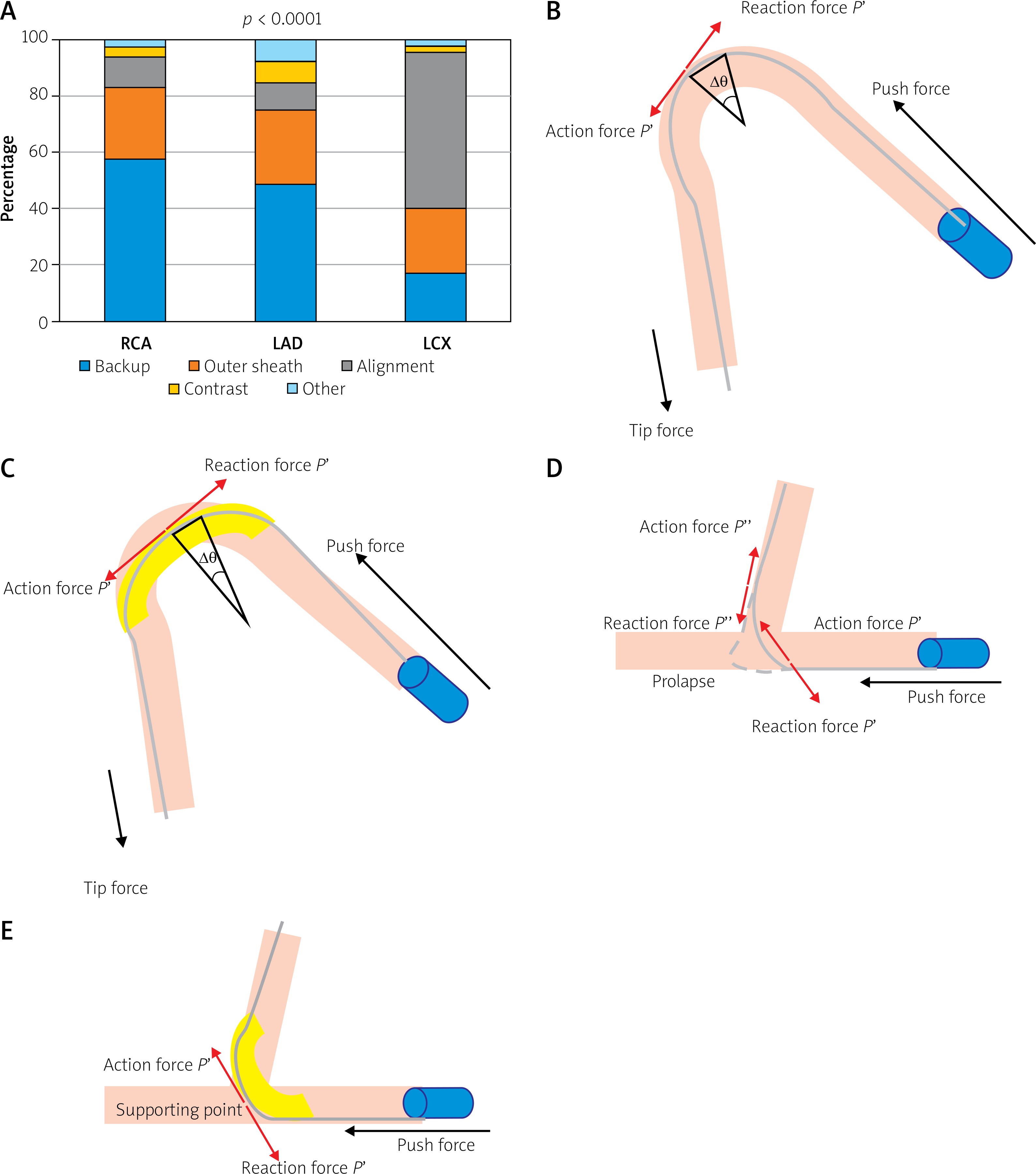
The primary indication for GEC is shown in Figure 1 A. The primary indication was similar for the RCA and LAD: increasing back-up of the guiding catheter was the most common reason, whereas improving alignment was the most common reason for the LCX. The indication for selective contrast injection was less common in all the three vessels. The device success rate was numerically lower in the LCX compared with the RCA and LAD. Therefore, the incidence of subsequent conversion to other methods was higher in the LCX. The overall procedural success was > 90%, and the difference of procedural success rate according to the target vessels was smaller than that of the device success rate. There were four complications: three coronary dissections in the RCA and one longitudinal compression of the proximal stent in the LCX.
Figure 1
Primary indication for guide extension catheter (GEC) according to the three target vessels and mechanistic effect of GEC in the right coronary artery (RCA) and left circumflex (LCX). A – the primary indication for GEC according to the target vessels. B – the shepherd’s crook RCA model. The push force is captured at the vertex of the angle. C – the effect of GEC in the shepherd’s crook RCA model. D – the acutely angled LCX model. The force escaping into the left anterior descending artery and the catheter shaft might prolapse. E – the effect of GEC for the acutely angled LCX. GEC can provide the supporting point and the push force is effectively transmitted
At a median of 363 (IQR: 222–382 days), target-vessel revascularization was undertaken in 21 lesions (Kaplan-Meier estimates 5.5% at 1 year; 13.2% at 2 year), located at the treated site in 14, distal to the treated site in five, and proximal in two. Only 1 patient experienced myocardial infarction (MI), who presented with stent thrombosis.
Discussion
The main findings of the present study are: 1) calcified lesions were more frequent in the RCA and LAD; proximal tortuosity was more frequent in the LCX and 2) the most common primary indication for the RCA and LAD was increasing back-up, whereas that for the LCX was improving alignment.
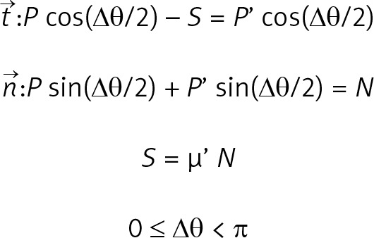
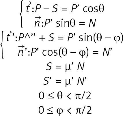
This study focused on the mechanistic effect of GEC as per target vessels. As shown in Figures 1 B–E, the supposed mechanistic effect of GEC to improve alignment between the catheter tip and the target lesion is different for each target vessel. For those lesions without bifurcation (Figures 1 B, C), the main effect of GEC is to decreases the Δθ by the stretch action and to decrease friction due to the smooth inner wall, as well as to increase back-up support by deep intubation [9]. As shown in Figure 1 D, the mechanics in LCX are different because of the non-existence of a supporting point due to the large side branch (LAD). GEC makes the supporting point, which results in a change in the model like Figure 1 E. This resembles the model of a shepherd’s crook RCA with GEC. As discussed above, the supposed mechanics of improving alignment using GEC in each target vessel are different. More details are discussed in the Appendix and Supplementary Figures S1 and S2.
This study offers an important point for interventional cardiologists because the necessity of GEC differs with each target vessel’s anatomy. With the RCA, some other techniques, such as using larger size guiding, buddy wire technique, stiffer guidewire, and anchoring balloon technique, can be helpful. However, with the acutely angled LCX, the operator must use GEC as the first choice. Moreover, in cases of severe calcified lesions, the smooth delivery of a drug-eluting stent and drug-coated balloon using GEC might improve the long-term prognosis [8]. In this regard, it is worthwhile to consider the differences in the primary indication for GEC according to the target vessels.
Only one study has previously described the primary indication for GEC between the RCA and left coronary artery (LCA) [6]. It was stated that the most common primary indication for GEC is to improve the alignment or selective contrast injection for the LCA and to increase back-up for the RCA. Nevertheless, as the bifurcation angle of the left main (LM)–LCX is larger than that of the LM–LAD [10], the primary indication for the LAD and LCX should be distinguished. If we integrate the primary indication for the LAD and LCX together and convert the ratio of the LAD and LCX (17 were used in LAD and 20 in LCX in reference [6]), the leading indication for the LCA is improving alignment.
In this study, the adverse event rates were acceptable, considering the lesion complexity and patients’ high-risk background (increased age, high prevalence of CKD, multivessel disease, and chronic total occlusion). It is of great concern that MI for atheroma progression of the proximal coronary artery might be triggered by GEC deep intubation. In this regard, the result of the present study revealed the safety of GEC facilitated PCI.
Although we adopted only one primary indication for each lesion, the actual mechanics were more complex. Furthermore, we ignored the deflection moment of catheters to simplify the model. However, considering the mechanistic effect of GEC, even in the simplified model, is important in choosing the best technique for each lesion.
Conclusions
The primary indication for GEC differed considerably among target vessels. Interventional cardiologists should consider the mechanistic effect of GEC to maximize its performance.
Conflict of interest
H.I. received lecture fees from Astellas Pharma Inc., Bayer Pharmaceutical Co., Ltd., Daiichi-Sankyo Pharma Inc., and MSD. T.M. received lecture fees from Bayer Yakuhin Ltd., Daiichi-Sankyo Co., Ltd., MSD K. K., Mitsubishi Tanabe Pharma Co., Nippon Boehringer Ingelheim Co., Ltd. Department of Cardiology, Nagoya University Graduate School of Medicine received research grants from Astellas Pharma Inc., Daiichi-Sankyo Co., Ltd., Dainippon Sumitomo Pharma Co., Ltd., Kowa Co., Ltd., MSD K. K., Mitsubishi Tanabe Pharma Co., Nippon Boehringer Ingelheim Co., Ltd., Pfizer Japan Inc., and Teijin Pharma Ltd.