
Purpose
Worldwide, basal cell carcinoma (BCC) and squamous cell carcinoma (SCC) are the most common cancers [1, 2]. Treatment of these types of neoplasms is very effective with surgical approach [3-5]. However, it may have location-related challenges. Due to frequent occurrence of such lesions in the facial region, surgical treatment may not be advisable due to potential mutilation and requirement of plastic reconstruction [6].
Skin surface brachytherapy is a standard treatment modality for non-melanoma skin cancers, and allows achieving local control in 93-95% of cases [7, 8]. This treatment method is one of the first applications of brachytherapy itself [9]. Main advantages include steep dose gradient and possibility of optimizing dose distribution, after the introduction of brachytherapy afterloader devices [10, 11].
One of the main challenges in facial region brachytherapy is vendor-delivered standard applicators, such as Freiburg flap or Valenzia/Leipzig applicators fixation. Reproducibility can be maintained; however, there are frequent problems with the fitting of applicator to the skin surface in pleated areas close to the nose, eyes, ears, or lips. Manually prepared individual moulds require technological facilities and, most importantly, well-trained staff, with highly developed manual skills to produce moulds [12, 13].
3D printing may be the answer to these problems, as low-cost printers are nowadays widely available, and open a new perspective to the idea of contact brachytherapy applicator preparation. Materials available for low-cost printers, such as acrylonitrile butadiene styrene (ABS) or polylactic acid (PLA), can be extruded in patterns and infill, creating objects of density and absorption of radiation close to water; therefore, they seem appropriate for such a purpose [14, 15].
The main aim of this study was to design and manufacture individual skin brachytherapy applicator using 3D printer. Additionally, the authors wanted to evaluate its’ feasibility in clinical application and early clinical results. This article presents the 3D-printed applicator preparation for a particular patient skin brachytherapy, using low-cost equipment and free software (apart from treatment planning system). We describe applicator preparation in a step-by-step workflow, its’ application on patient, patient’s compliance, and early clinical results up to ten months after treatment. The presentation of procedure is supported by a series of relevant figures and, of note, concise video material available at https://player.vimeo.com/video/690945494?h=66d6be990f.
Material and methods
Patient
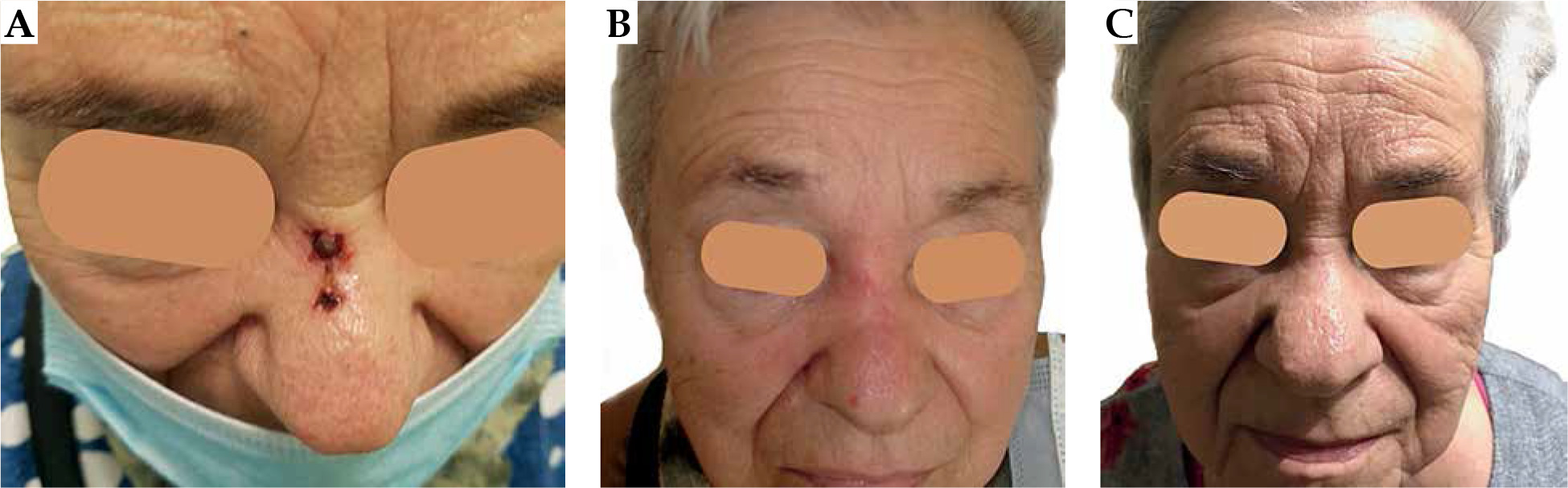
A seventy-eight years old female agreed to participate in the project. The patient was selected due to challenging recurrent tumor located in the nose bridge (Figure 1A – initial clinical presentation). She was not considered as a surgery candidate, and was referred to brachytherapy department from the surgical facility. Primarily, a nodule appeared at her nose in spring 2019. A 1 cm nodule was surgically resected in September 2019. Pathological report revealed basal cell carcinoma (nodular type) resected with a close side margin of less than 0.5 mm (assessed as doubtful), and minimal base margin of 1 mm, pT1. After a year, the tumor recurred as two neighboring ulcerated lesions measuring 12 mm and 4 mm, rT1(m). A biopsy taken in February 2021 confirmed a BCC recurrence, with BerEp4 (+), EMA (–) and S-100 (–) immunophenotype. The patient performance status was assessed as grade 1 according to the Eastern Cooperative Oncology Group scale [16]. The patient had the following comorbidities: arterial hypertension, diabetes mellitus, bronchial asthma, and chronic obstructive pulmonary disease. Finally, she was proposed ambulatory superficial high-dose-rate (HDR) brachytherapy scheduled in 6 fractions by 7 Gy, two fractions a week, according to the American Brachytherapy Society consensus statement for skin brachytherapy [17]. In order to participate in the project, she signed an informed consent.
3D printer
For the applicator’s production, we used Original Prusa i3 MK3S+ printer (Prusa Research, Prague, Czech Republic), a device with possibility of printing objects up to 25 cm × 21 cm × 21 cm. Since possible heights of printed layers are in the 0.05-0.35 mm range, printouts can be very precise. The device is equipped with a 0.4 mm diameter extruder nozzle, which can be exchanged with a more precise or thicker nozzle to speed up the process of printing. The printer is equipped with a heated working table that allows using a wide range of materials, including polyethylene terephthalate glycol-modified (PETG), ABS, acrylic styrene acrylonitrile (ASA), PLA, polycarbonate (PC), nylon, etc., due to adjustable temperature of the extruder and working table. The producer provides the device with user-friendly slicer software, allowing verification and adjustment properties of a digitally prepared printout. Despite its’ wide functionality, the device is inexpensive, costing nearly 1,000 USD.
PLA filament
PLA filament is aliphatic linear polyester obtained from natural resources, such as corn or sugar cane. Due to its’ bio-degradability, bio-compatibility, and non-toxicity, it is popular and easily used in industry and complex biomedical applications [15, 18]. PLA is one of the most common and easy to print materials, characterized by low processing shrinkage. It is by far, the most widely used printing material, and due to its’ thermoplastic proprieties, it is suitable for 3D printing with fused deposition modelling (FDM) method. The recommended temperature of the nozzle ranges from 175°C to 235°C. PLA is a material that allows for relatively fast printing within a speed range of 60-80 mm/s.
Hounsfield units (HU) of objects printed with 90% infill of PLA are close to water, ranging from –36 HU to 44 HU, depending on X-ray energy [14, 15]. Printouts with lower infill contain more air gaps; therefore, the density decreases. Also, PLA is a low-cost material (25-30 USD per kilogram), and for an applicator, the material required is 50-150 grams; thus, there is no need to lower the infill to reduce costs.
Applicator design
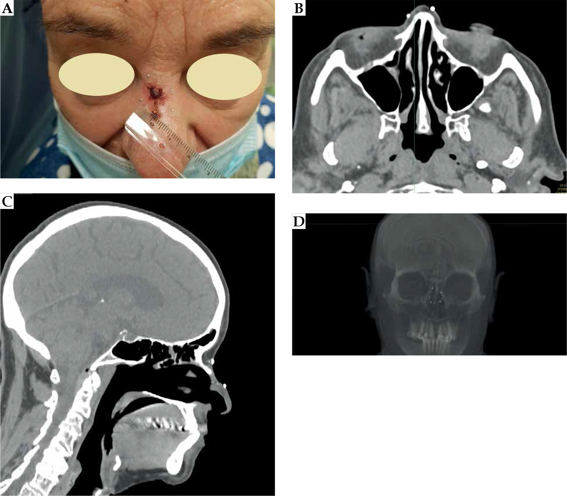
At the patient’s first visit, a therapeutic decision to perform contact brachytherapy was made. Fiducial markers were placed on the skin surface to enclose the treated lesion with a margin of 5 mm (Figure 2), and a CT scan with 1 mm slice thickness was performed. The patient was scheduled to start the treatment within two weeks (at least a week to prepare the applicator and perform quality control), according to occupancy of the brachytherapy department.
Fig. 2
A) Fiducial markers placed on the skin surface of the patient. Markers enclose the treated lesion with a 5 mm margin. B) Fiducial markers on transversal CT images. C) Fiducial markers on sagittal CT reconstruction. D) Fiducial markers visualized in 3D volume CT reconstruction
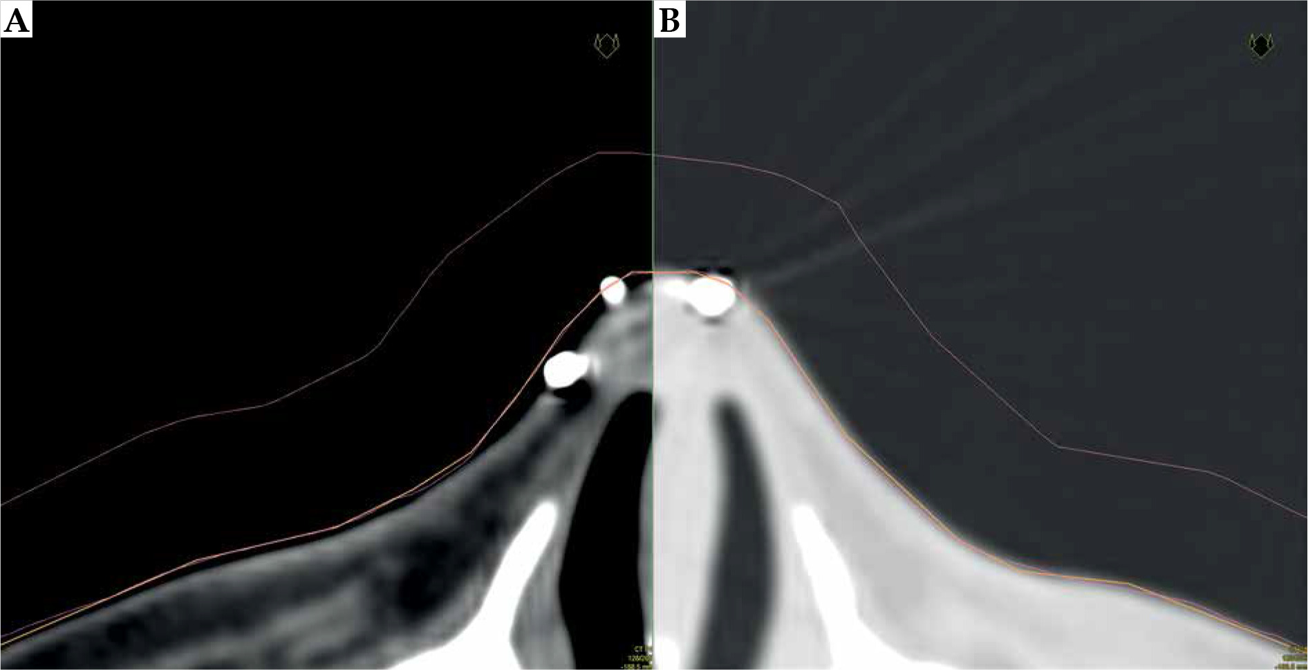
In Oncentra Brachy 4.6 (Nucletron, an Elekta Company), a physician reconstructed target volume on CT scans based on physical examination and markers. Next step was the contouring of patient’s external boundaries, using a magic wand or automatic contouring tool in the lung imaging window (center at –600 HU and width of 1,600 HU) (Figure 3). With these settings, it was possible to prepare an applicator that was well fitted to the surface of the patient’s skin. Using a soft tissue imaging window (center at –40 HU and width of 350 HU), applicator was too tight, which we have learned while developing the procedure, therefore, it may not be comfortable for the patient due to a sub-millimeter discrepancy.
Fig. 3
A) A CT scan with visible gap between reconstructed structures (external: orange, applicator: pink) in soft tissue HU (Hounsfield unit) window. B) The same structures are visualized in the lung HU window (center: –60 HU, width: 1,600 HU). The adjacency is much better, and there are no air gaps visible between structures and the patient body
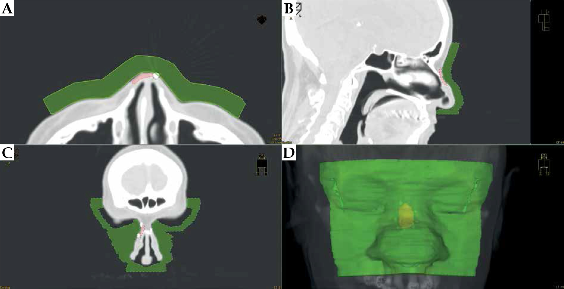
On the outer surface of the patient, a bolus of 1 cm thickness was generated, covering the reconstructed lesion area, with additional several centimeters margins. This bolus was the designed body of applicator. The bolus was investigated and trimmed scan-by-scan to ensure it did not cut into or stand out of the patient’s body (Figure 4).
Fig. 4
CT scans and the applicator visualization (green) on transversal (A), sagittal (B), and coronal (C) sections. Recesses for eye shielding are visible on the coronal section. D) 3D reconstruction of the designed applicator body
Subsequently, catheter paths in the applicator were designed. In brachy planning section of TPS, catheter paths were drafted at around 5 mm from the skin surface and spaced every 5 mm to 7 mm distance, covering target volume. It was crucial to design the catheters; the tip end and the connector end extended beyond the body of the bolus, so that the channels for the catheters were not blind-ended (Figure 5). Channel’s curvature was examined if there were no problems with catheter braking inside their paths or too big friction of control wire before the treatment. After the source paths were designed, dwell positions over target volume were activated. Dose was normalized and optimized on dose points located on the inner surface of target volume. Afterwards, dose distribution was optimized graphically (Figure 6). If the dose distribution in target volume and OARs was not satisfactory, catheter paths should be re-arranged and dose distribution re-planned. After each source path re-designing, it should be inspected for curvature and distance from the skin.
Fig. 5
The reconstruction of applicator body (green) with planned catheter paths (light blue). There is a visible 3D reconstruction of target volume (pink). Catheters extend outside the body of applicator
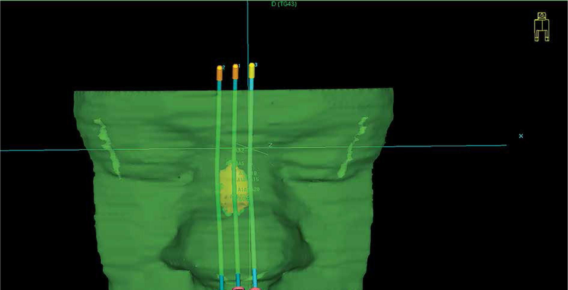
Fig. 6
A visualization of pre-planned dose distribution on CT scans. Red dots represent active dwell positions, and isodoses are described in the images
When dose distribution was satisfactory, the plan prepared for the applicator printout should be saved separately from the pre-plan. All dwell positions must be activated (software Beben – DICOM to standard triangle language [STL] generates catheter paths according to active dwell positions). Further, DICOM radiotherapy structures (RTStructures) and radiotherapy plan (RTPlan) files need to be exported.
Beben – DICOM to STL
Beben – DICOM to STL created by Marek Boehlke is an open-source free software, which extracts coordinates of points being vertices of polygons of chosen structure from RTStructure file and then, processes them into 2D forms. By doing this, layer-by-layer, it computes a three-dimensional solid. For channel creation in final 3D applicator, a structure showing volume of the applicator itself was exported first, and then air tracks were generated. Regarding channel shape, the program extracted data from RTPlan files containing active source dwell position coordinates in the same coordinate system as the applicator vertex coordinates. For smooth catheter insertion, diameter of tunnels was set as 3 mm.
The whole process is summarized in Table 1 and presented in the attached video material (https://player.vimeo.com/video/690945494?h=66d6be990f). In Beben – DICOM to STL software, there is a ‘Basic’ tab in the main toolbar where ‘Import DICOM file’ icon is placed. After clicking this icon, a dialog to browse for DICOM RTStructure file pops up. A list of reconstructed structures is shown when a DICOM file containing reconstructed structures is chosen. The applicator design should be selected, and the software loads all the contours of this structure. Next, after clicking ‘Catheters’ tab, a new pop-up window appears in the header. Choose ‘File’ in the main toolbar, then ‘Load catheters from RtPlan DICOM File’ is available. Again, a new dialog appears, and RtPlan DICOM file containing source active dwell positions should be chosen. In the field on the right, catheter paths appear within the contours of the bolus. In the ‘Basic’ tab, there is an icon: ‘Create a surface using the raster method’. After clicking it, the applicator with catheter paths is created. Next, in the ‘Basic’ tab, there is ‘Save surface in *.stl file’.
Table 1
Instruction and check list to transform DICOM structure and plan files into a model for 3D printing, using Beben – DICOM to STL software
In the present study, 4.03 version of Beben – DICOM to STL was used. The software can be downloaded from the website: https://sourceforge.net/projects/beben-dicom-to-stl.
Slicer
The last step (after the applicator with channels for catheters was designed) was to generate a g-code file (computer numerical control programming language file used to control automated machine tools) in a slicing software dedicated for a printer. Slicer is a computer program converting a 3D object to instructions for a 3D printer on how printout should be performed. G-code is the most widely used computer numerical control (CNC) programming language. It is an instruction for a 3D printer containing movement paths, nozzle temperature, material extrusion speed, and all information needed to perform a printout.
There is a possibility to choose diverse infill patterns. It is essential to select the same infill pattern in printouts for patients as used in plans for quality assurance. The infill pattern affects durability, stiffness of a printed object, and print time, but may also affect density. For example, presented applicator with a grid pattern infill and printout takes 9 hours 28 minutes, gyroid infill pattern takes 15 hours 16 minutes, and rectilinear design takes 7 hours 54 minutes. In this study, we used a grid pattern with 90% infill.
Applicator assembly
The printed body of applicator was inspected for sharp edges and clumps of PLA left after printing. Suppose lumps were near lumens for catheter insertion or on the surface contacting patient’s skin; they were removed with a file. The next step was to insert commercially available single-leader 6F catheters (Nucletron, an Elekta Company), as the source should only encounter materials provided by a certified vendor. If a catheter passes freely through the lumen, the connector end of each catheter is secured in place with a dedicated button (a glue may be used if necessary). It assures no displacement of the catheter during whole treatment period. The pre-plan was exported to afterloader, and the applicator was connected. The pre-plan was executed to ensure the source can pass through each catheter (Figure 7).
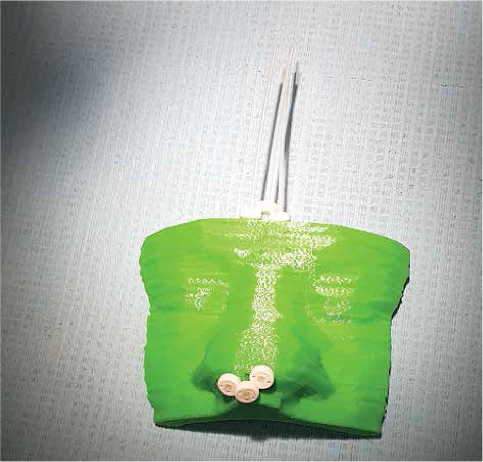
Fig. 7
A photography of 3D-printed applicator. The catheters’ tip ends are located on the patient’s nose
Additionally, the pre-defined places for the eye lead shields were inspected. The dedicated lead sheet pieces were cut and adjusted in place, then removed to avoid artifacts in CT imaging.
Treatment planning
On the day scheduled for treatment planning, the patient had the applicator fitted in place (Figure 8). Since PLA is not a certified material for medical use, the treated area was covered with a transparent surgical drape [19]. The applicator was fitted in a CT room and secured with dressing plaster. A CT scan was performed with a slice thickness of 1 mm, and the applicator was removed. The eye lead shields were put back and glued in before first irradiation. Target volume and OARs were contoured, catheters were reconstructed, and dose distribution was planned again on new CT images. Treatment plan was prepared for the applicator to consider slight differences between pre-planned catheter positions and possible applicator displacement. The patient’s skin would always slightly bend under even a small weight of the applicator. Fixation with a dressing plaster or a bandage may also distort the patient’s skin surface. The patient was treated with prescribed dose and fractionation.
Results
The patient’s applicator had three channels to cover the target with a prescribed dose and maintain doses to OARs at assumed levels. The printed applicator precisely fitted the patient’s skin surface; its’ placement was easily reproducible regarding placing and securing (Figure 9). All dose-volume histogram (DVH) parameters from the pre-plan and plan delivered to the patient are presented in Table 2. Clinical target volume (CTV) was slightly broader in the treatment plan (0.34 cm3 vs. 0.31 cm3), and doses given to CTV were lower, except for V150, which was higher for the realized plan (1.15% vs. 1.83%). All reported doses to OARs were lower in the realized plan.
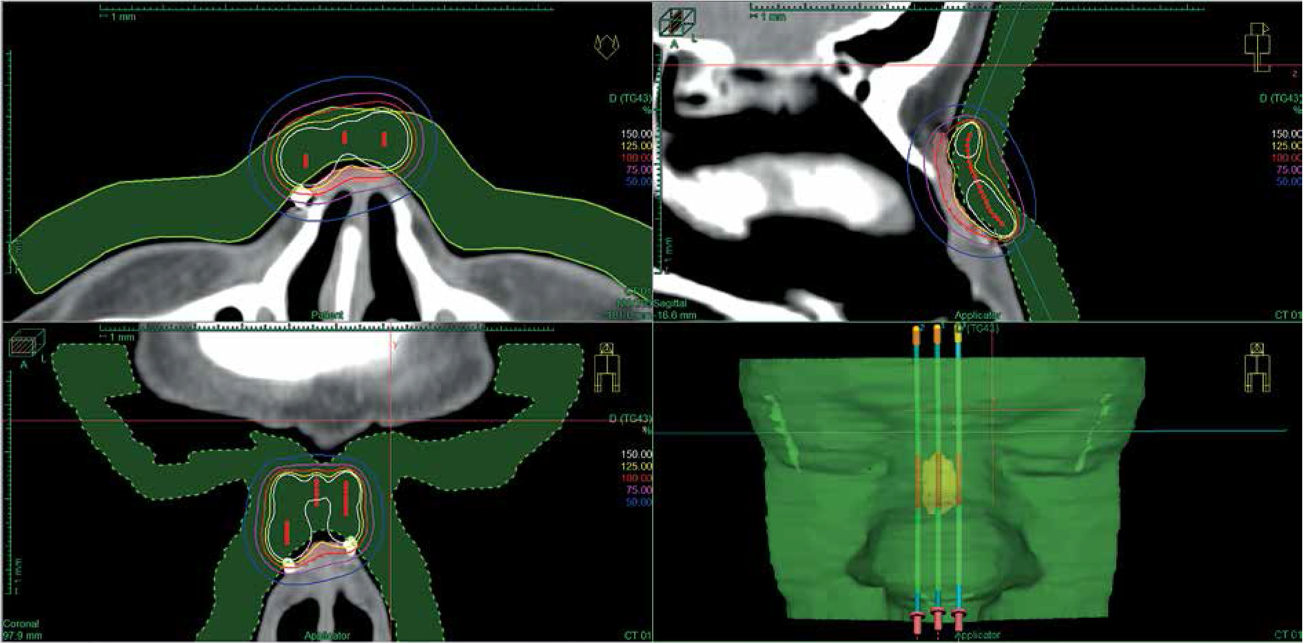
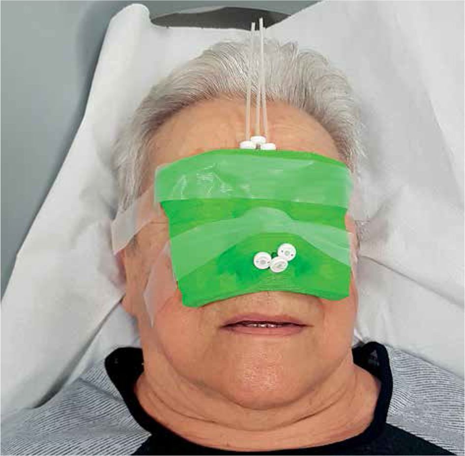
Fig. 9
CT scans of the patient with a placed applicator with dose distribution of accepted treatment plan. A) Transversal section with visible small air gaps in soft tissue HU window. B) Good target volume coverage with 100% isodose (red line) visible in the sagittal section. C) Transversal section in the lung HU window. In this visualization, the applicator fits very well and air gaps are much smaller. D) Dose distribution of calculated treatment planned presented in the sagittal section in the lung HU window
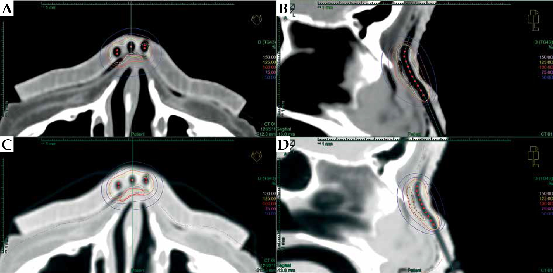
Table 2
Dose distribution parameters for reconstructed structures calculated for pre-plan and realized treatment plan
V100 – volume receiving at least 100% of prescribed dose, V150 – volume receiving at least 150% of prescribed dose, V95 – volume receiving at least 95% of prescribed dose, D90 – lowest dose received by 90% of delineated volume, D100 – lowest dose received by 100% of delineated volume, D2 – highest dose received by 2 cm3 of delineated volume, D0.1 – highest dose received by 0.1 cm3 of delineated volume
During the whole procedure, the most time-consuming process was bolus delineation and verification of matching with the patient’s CT outline. It was crucial to prepare a well-fitted and comfortable applicator. Next was the design of lumen paths; they were gently curved, catheters could pass freely, and the source would not obstruct. The whole pre-planning procedure with plan calculation and verification took two hours. The preparation of the applicator’s project and generating g-code file took 30 minutes. The time of applicator printout was 9 hours and 27 minutes, and was performed conveniently overnight, without a need for supervision of our staff. There was 97.83 g of PLA needed to print the applicator.
The treatment lasted for 16 days and was well-tolerated. The patient and staff did not complain about the 3D-printed applicator or any allergic reactions. However, the treated region was covered with medical drape before each fraction.
At the first follow-up visit after completion of the treatment, clinical results of five weeks showed a complete remission with slight erythema (Figure 1B). After ten months post-treatment, no clinically relevant late effect was observed, and the patient presented excellent cosmetic results (Figure 1C). The patient is under local control until the last day of follow-up.
Discussion
A fused deposition modelling is a widely available and an inexpensive solution to produce material objects designed in a digital environment. It is increasingly used in medicine, and several years ago had been introduced into brachytherapy. Preparation of individual moulds for skin brachytherapy is often challenging, and standard applicators supplied by vendors are sometimes not applicable due to inconvenient lesion locations. Moreover, it is time-consuming and requires experienced staff. However, individual applicators deliver prescribed dose more precisely and safely in irregular localizations, because of better fitting and more dependable assembly. Casey et al. reported a better fitting of a 3D-printed applicator and reduced air gaps between the applicator and skin of the patient using a hand-fabricated mould [20]. One most common localization of an occurrence of skin cancer is the face; therefore, there is a need of wide implementation of 3D-printed individual applicators in brachytherapy.
On the other hand, there are some data on manufacturing of an applicator for a patient with a dental impression [21, 22]. However, it requires specialized workspace, manual skills, and experience. It is challenging and expensive to hire an additional specialist in many brachytherapy departments or organize a dedicated room for a workshop. 3D printing seems to be a solution for these problems, as purchasing a low-cost 3D printer with a filaments supply is an expense lower than 1,500 USD. A room needed for this equipment is small, as it is a compact device and can be put on a desk; it weighs less than 10 kg. A 3D printer is not too noisy during operation, and printing with PLA does not emit unpleasant or dangerous fumes; therefore, it does not need a dedicated room.
Designing a 3D-printed skin applicator is similar to preparing a reliable CT-based pre-plan that can be done by medical physicist. The procedure is not very time-consuming as the longest part, printing of the applicator, is performed automatically and may be executed unattended or even overnight. Inspecting the outline of patient in TPS is very important, as often the polygon defining patient’s external contour have a limited number of vortexes. Adjusting the TPS contour with a free-hand or pearl contouring tool to be visible on optimal HU window, patient outline allows preparing a well-fitting and comfortable applicator. It can be done by a dedicated electroradiologist or radiotherapy technologist.
The main issue regarding FDM implementation into brachytherapy practice was the transfer of source path coordinates and bolus structure from treatment planning system to slicer software. Our software, Beben – DICOM to STL, resolves this issue. Active dwell positions and vortexes of polygons defining the bolus solid on each CT slice are extracted in the same coordinate system. The program is intuitive and does not require an information technology background to help a medical physicist working clinically.
Finding a proper settings for a specific printer and printing material is of the most importance [23]; therefore, adequate quality assurance measures should be introduced before treating patients. Verifying geometrical reproducibility is essential to confirm whether there is no resizing during design procedure, as changes in size may lead to a discrepancy of applicator. Harris et al. reported on a sub-millimeter agreement in physical dimension of printed objects with designed models [19]. The printed applicator should be inspected for compliance in terms of shape and size. Verification of catheter lumens’ patency is of utmost importance. Catheters should pass through easily, and a pre-plan should be executed with an afterloader to ensure the source would not meet any obstructions.
Due to possible shift of the applicator or inaccuracy of printing, CT for planning should be performed. Dose calculation and optimization should be performed for the printed object. A tissue can deform or stretch by applicator fixation on its’ surface, and it should be considered during treatment planing. In our experience, the difference in shape of treated region does not significantly impact the matching surface of applicator and skin. Still, in some locations, such as the earlobe, the whole target volume could shift about OARs. In these regions, dose distribution might change significantly. However, DVH parameters of target volume and OARs may be maintained on pre-planning level and therapeutic goals achieved.
3D-printed applicators for brachytherapy have been previously presented. A 80-90% printout infill of PLA provides electron density close to water [14, 15]. Delivered dose distributions in anthropomorphic phantom have been verified and, for surface applicators, proven to be consistent with doses calculated in TPS [18]. These findings prompted us to take our research to the next step, introducing 3D-printed applicators to our clinic.
Polylactic acid is a bio-compatible and bio-degradable material [24-26]; however, low-cost materials primarily used in 3D printing do not have any certification for medical use. There are certified filaments for FDM technology on the market, but they are sold in small quantities and available on request only [27]. 3D-printed applicators for skin brachytherapy contact only an uncompromised skin. Thus, the certified bio-compatible coating is used to secure it. During the treatment period, neither deformation nor any other deterioration of the applicator were noticed. Moreover, during the time of adjusting the printer and control printings, no allergic reactions were observed in the staff.
Conclusions
A low-cost 3D printer and widely available, and PLA filaments seem feasible to produce individual contact applicators for skin brachytherapy. Beben – DICOM to STL and the presented workflow appear to be a convenient and straightforward tool that each brachytherapy team should verify before clinical use. A successful clinical results, with low toxicity and excellent cosmetic results appeared as anticipated.


