
Purpose
Skin cancer
Keratinocyte carcinoma (KC), or cancer deriving from keratinocytes of the skin, is the most common type of cancer worldwide. Keratinocyte carcinoma consists mainly of basal cell carcinoma (BCC) and cutaneous squamous cell carcinoma (cSCC) [1]. Recently, KC term has been gradually replacing non-melanoma skin cancer (NMSC), as it better reflects the specific (keratinocyte) origin of the cancer [2]. Even though most cancer registries in North America and other countries do not collect data on many KCs due to difficulties in tracking case and relative success of most treatments [3], some estimate that over 5 million patients are diagnosed every year solely in the USA [4], with many patients having more than one KC diagnosis [5]. Surgery is the standard treatment modality for KC. The main goal of treatment is to remove cancerous lesions while maintaining cosmesis and tissue function [6]. There are, however, instances, where surgical techniques would yield inadequate resection of the lesion, or possibly poor cosmetic or functional outcomes due to location of disease. Some patients may not be eligible for surgery because of associated comorbidities or they simply refuse such treatment. In these cases, radiation therapy can play a prominent role in the treatment of KC, using external beam radiation therapy (EBRT) with electrons, photons, superficial, or orthovoltage radiation, which can all successfully treat KC. However, irregular topologies with sharp gradients can present problems when attempting to distribute a therapeutic dose using EBRT homogenously and limit the dose to surrounding tissues. In these specific cases, brachytherapy (BT), the treatment of a lesion using radioactive sources placed adjacent to or directly within cancer, can be used to achieve high control rates as well as promising cosmetic and/or functional results [7].
Brachytherapy
There are two primary types of BT for the treatment of skin, including superficial and interstitial [8, 9], and the depth of disease determines which type is appropriate. Interstitial BT, where catheters are directly implanted in the lesion, is warranted generally for skin lesions ≥ 5 mm in thickness, which is out of the scope of this article [10]. Superficial BT, also known as ‘contact BT’ or ‘plesiotherapy’, is the use of radionuclide or electronic sources to treat cancerous lesions < 5 mm in thickness [6]. These sources are guided through catheters in a specialized mould, or an applicator temporarily affixed to the skin. Common radiation source types include iridium-192 and cobalt-60 [9]. GEC-ESTRO ACROP recommendations in skin brachytherapy states that for lesions less than 5 mm in thickness, standard surface applicators and flaps are indicated on regular surfaces, while customized applicators can be used for irregular sides [10].
Brachytherapy offers many known benefits over EBRT, such as rapid dose fall-off with distance from the source, thus reducing dose to underlying tissues and nearby organs at risk, hypo-fractionated treatments’ regimens, which yield comparable efficacy and cosmetic results [11, 12] while limiting patient visits, and customized applicators that can conform to the variable contours of the skin, allowing better approximation to skin surface. In superficial BT studies, for small and shallow KC lesions, local control ranged from 96.2% to 100% for up to 66 months of follow-up [13-21]. Additionally, superficial BT has been shown to offer superior results in terms of conformity, dose coverage, and tissue sparing ability compared to EBRT when treating areas of the head and neck, especially the nose and ear lobes [22].
There is a growing trend towards digitally designing applicators tailored to each patient’s unique anatomy and employing additive manufacturing (AM) techniques, commonly referred to as ‘3D printing’. This review discusses AM and its association with superficial high-dose-rate (HDR) BT, applicator creation process, quality assurance measures, and clinical applications.
Traditional applicators – benefits and drawbacks
Many cancer centers use standardized applicators for superficial BT treatment. Flexible, flap-like applicators are commercially available. These are a viable option for some large skin cases, due to consistent catheter spacing and flexibility as well as the ability to cut the flap to specific dimensions or affix it to other immobilization devices to improve reproducibility [23]. However, the flap applicators limit how close the sources can approach the skin and how well the flap geometry conforms to rapidly varying skin topology. Treating small areas is also challenging with these flap-based applicators. There are other commercial products available, such as Leipzig and Valencia conical applicators, which can treat small, planar areas (2-3 cm diameter). Still, these are not ideal over variable topologies. For treatments of irregular, curved surfaces necessitating customized devices, skin applicators have taken the form of moulds manually crafted within a cancer center either by radiation therapists or dosimetrists. Manually creating a mould involves laboriously forming a stone or gypsum plaster replica of patient’s anatomy, and then applying thin pieces of heated wax, plastic, or silicone [24] that are interweaved with catheter paths overtop the area of interest. Ensuring the catheter paths are consistently spaced and are at an appropriate distance from skin across the entire length of track can be challenging. Traditional manual mould preparation can also lead to air gaps between mould and skin surface and/or between mould layers.
Additive manufacturing in superficial brachytherapy
Clinical need for additive manufacturing applicators
The variations in contours among patients and the steep physical gradients in regions like the head and neck, where KCs are most common [25], necessitate customized BT solutions. Recently, with the rise of inexpensive yet robust mould creation options, more healthcare institutions have access to AM technology. AM is not new to radiation therapy nor limited to BT. Bolus [26], phantoms [27], immobilizers [28], and field-shaping devices [29] are a few of the other areas in RT, where AM technology has been incorporated. AM applicators are an attractive solution, as they enable almost exact replica of a patient’s surface as well as fully customizable catheter tracks. These applicators can potentially lead to sophisticated dose modulation through precise catheter placement, achieving a more homogenous skin dose. There is a growing interest in the development of AM applicators for skin BT. There is, however, a lack of review articles, and the latest guidance document from AAPM and GEC-ESTRO acknowledges that neither a standard of care nor comprehensive guideline exists yet for surface brachytherapy, let alone the inclusion of AM applicators [23].
Current literature profile of additive manufacturing in superficial brachytherapy
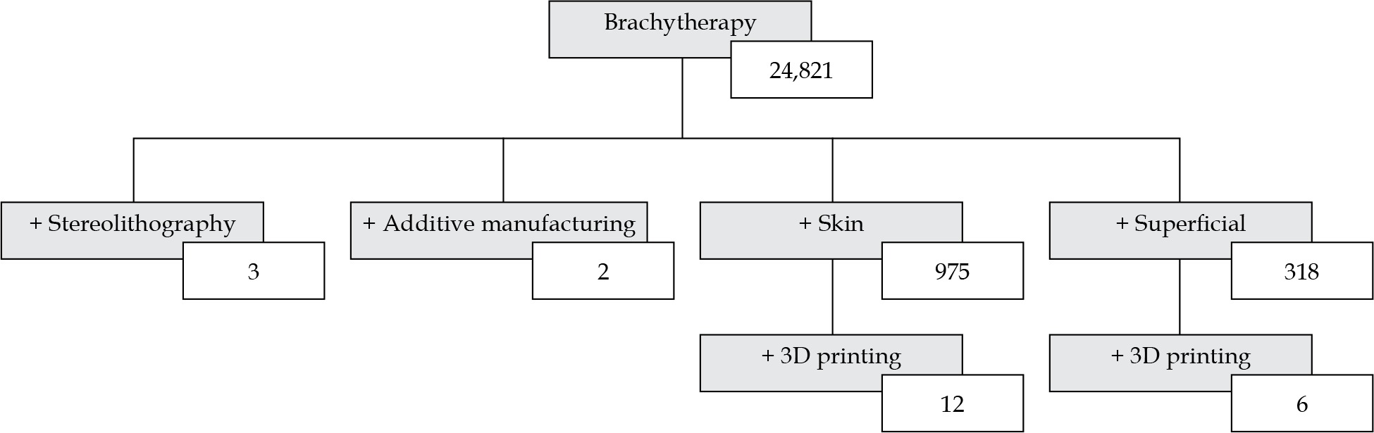
This paper is a review of the present state of AM in superficial skin BT. Keyword searches in the PubMed database with no date restrictions to find relevant articles were used. A publication was considered relevant for this review, if it discussed a clinical case, material dosimetric assessment, proof-of-concept study, or economic feasibility study of AM in superficial BT. PubMed was queried 4 times between January and June 2020. Medical subject heading search terms, included variations of ‘brachytherapy’, such as ‘skin brachytherapy’, ‘plesiotherapy’, ‘contact brachytherapy’, ‘superficial brachytherapy’, and ‘interventional radiotherapy’. The general search terms ‘mould/mold’ and ‘applicator’ were also used in the searches. Technology-specific search terms included ‘additive manufacturing’, ‘3D/three-dimensional printing’, ‘fused deposition modeling’, and ‘stereolithography’. Figure 1 shows an example of a database query. While there were generally very few results for each group of search terms, there were many different groups of terms that yielded different, yet relevant publications.
Fig. 1
Keywords and the resultant number of publications found through searches in the PubMed database up to July 2020. (+) denotes adding a term to a parent search term
After including additional abbreviated keywords, 28 publications were found for AM in superficial skin BT, which formed the basis of this review. These included 8 clinical case studies [30-37], 7 physical and dosimetric evaluations [38-44], 6 proof-of-concept cases [45-50], 6 design process assessments [51-56], and 1 economic feasibility study [57]. All these articles, except for one, were published since 2015. In a similar review of three-dimensional printing use throughout the entire field of radiation oncology, 21 publications were discussed relating to general BT applicators [58], with the vast majority of these also originating from the last 5 years. AM in superficial BT as well as radiation oncology in general is in its early stages but quickly gaining clinical interest and recognition.
Benefits over conventional moulds
Additive manufacturing offers many benefits over hand-fabricated moulds, mainly that production of the applicators is consistent and reproducible. Additionally, multiple virtual moulds can be created to determine which would best suit a patient’s anatomy with ease, and dosimetry can be optimized prior to fabrication. In contrast, significant changes to a manual mould after its completion take considerable effort or requires another mould altogether. Although AM applicators can take several hours to print, the printing can be done without oversight. Furthermore, AM applicators can be designed directly from a patient’s contours from computed tomography (CT) scans or direct surface scanning technologies. The patient only needs to be present for a quick, contactless scan, as opposed to extended episodes of making a plaster cast of the area in question [57]. The custom AM applicators can be designed to fit tightly and securely to the skin, minimizing air gaps better than conventional approaches, even when there are slight variations in anatomy [42]. Furthermore, the offset between the catheters and the skin surface of the patient can be carefully adjusted to achieve a higher dose to more deep-seated tumors, or to achieve sharper dose drop-off adjacent to organs at risk and reduce risk of air gaps. Given the digital nature of AM applicators, constant catheter distance and spacing across the target surface are possible enabling predictable dose modulation, and better agreement between planning goals and delivered dosimetry [33]. Further, AM enables the option of incorporating shielding into the applicator – the initial print can have cavities that can be filled with shielding materials [30, 33]. Lastly, most of the AM applicator creation process is digital. This can potentially lead to sharing of code and digital workflows. Naturally, there is a significant potential for automation and optimization in the future.
Process of additive manufacturing
According to the International Organization for Standardization (ISO) and the American Society for Testing of Materials (ASTM), AM is the “process of joining materials to make parts from 3D model data, usually layer upon layer” [59]. In regards to the term ‘3D printing’, the latest standards document, ISO/ASTM 52900-15, states that it is “the fabrication of objects through the deposition of a material using a print head, nozzle, or another printer technology” but also notes that the term “is often used in a non-technical context synonymously with AM; until present times this term has in particular been associated with machines that are low end in price and/or overall capability” [59]. Simply, it is a general term that describes only a subset of technologies within the broader family of AM [60]. This widespread adoption of the term ‘3D printing’ in medicine to refer to all AM processes may present a barrier in the future, namely for knowledge dissemination and research [61].
Outside of medicine, AM has existed for many years, and several groups of AM-based technologies have been established. The first type of AM was developed in the 1980s by Charles Hull. Through his company, 3D Systems, Inc., Hull patented a technique known as ‘stereolithography’ in 1986, which was able to create plastic prototypes much quicker than the traditional techniques of formative or subtractive manufacturing, without their associated imperfections [62]. Since 1986, there have been many AM techniques developed, with the commonality that a 3-dimensional object is constructed sequentially, a single-layer at a time.
According to the ASTM, there are 7 distinct groups of AM technologies based on the process of layer formation of the resultant object [63]. These categories include vat photopolymerization, material extrusion, powder bed fusion, sheet lamination, binder jetting, material jetting, and directed energy deposition. Moreover, each category is composed of several similar proprietary and open-source technologies [64]. Material extrusion (ME), the “process, in which material is selectively dispensed through a nozzle or orifice” [59], is the most common form of AM used in radiation oncology [65] and superficial BT. Within ME, the major technology is fused filament fabrication (FFF). FFF is equivalent to fused deposition modeling (FDM), currently a trademark of Stratasys, Inc. FFF use is generally widespread because of relatively low associated costs, acceptable resolutions, and suitable physical and dosimetric properties of the materials involved [65] compared to other technologies. Vat photopolymerization (VP), the “process, in which liquid photopolymer in a vat is selectively cured by light-activated polymerization” [59], and material jetting (MJ), the “process, in which droplets of build material are selectively deposited” [59], are also seen to a lesser extent through stereolithography apparatus (SLA) and PolyJet (PJ) technologies, respectively. The other AM processes are not currently used in superficial BT, and instead, are likely deployed for highly precise industrial tasks with more robust materials, such as lasered metal powders for jet engine component creation [66]. Furthermore, each technology requires different types of materials, with some crossover among the technologies. Material selection considerations, such as biocompatibility, sterilization, and dosimetric properties as well as other physical characteristics will be further detailed in the quality assurance section of this review. Until recently, most AM methods have been restricted to industrial manufacturing companies that had the necessary capital and the expertise to purchase and operate the expensive equipment. With the rapid progress within the field of AM, purchasing desktop AM devices, such as FFF machines, is now economically feasible for healthcare facilities.
Components of additive manufacturing in creation of superficial brachytherapy applicators
The general workflow presented in the existing literature for generating AM applicators can be described in 3 steps: 1. Patient’s anatomy modelling – obtaining a surface or CT scan and identifying the target; 2. Digital processing of patient data – designing the print and sending the instructions to the printer; and 3. Printing the physical applicator – physically forming the object. The following sections discusses the various ways, in which these three steps have been clinically implemented. A summary of pertinent information is shown in Table 1.
Table 1
Classification of hardware, software, and materials used in some of the publications in this review
| Author(s) [Ref.] | Study relevance | Year | Anatomy modeling | Digital processing software | AM device(s) | AM category and technology | Material(s) | Material certification(s) |
|---|---|---|---|---|---|---|---|---|
| Aldridge et al. [37] | Case study – finger (abstract) | 2016 | CT | Mimics and 3-Matic software (Materialise, Belgium) | Objet500 Connex1 (Stratasys, Inc., USA) | MJ – PJ | TangoPlus (Stratasys, Inc., USA) | None |
| Taggar et al. [35] | Case study – fingers (abstract) | 2019 | Dental alginate, laser scan, CT | – | – | VP – SLA | Accura ClearVue (3D Systems, Inc., USA) | USP class VI |
| Casey et al. [31] | Case study – leg | 2019 | CT | – | ProJet MJP 2500 Plus 3D printer (3D Systems, Inc., USA) | MJ – MJP | VisiJet M2 ENT (3D Systems, Inc., USA) | None |
| Clarke [30] | Case study – nose | 2016 | Discovery STE CT scanner (GE Medical Systems, USA) | Blender (open-source) | Lulzbot Taz 5 (Aleph Object Inc.) | ME – FFF | NinjaFlex (NinjaTek) | None |
| Jones et al. [34] | Case study – nose | 2017 | Somatom Definition Multislice CT (Siemens, Germany) | Mimics Medical 18.0 & 3-Matic Medical 10.0 (Materialise NV, Belgium), Matlab (MathWorks, USA) | Objet 500 Connex1 (Stratasys, Inc., USA) | MJ – PJ | TangoPlus FullCure 930 (Stratasys, Inc., USA) | None |
| Lecornu et al. [33] | Case study – nose | 2019 | CT | Rhinoceros 3D & Grasshopper (Robert McNeel & Associates, USA), Simplify3D (Simplify3D, USA) | – | – | PLA1 | None |
| D’Alimonte et al. [32] | Case study – penis | 2019 | Dental alginate (Jeltrate, Dentsply Intl Inc., USA), Dental stone (Whip Mix Corp., USA), laser scan, CT | Meshmixer, Inventor (Autodesk, CA, USA) | – | VP – SLA | Accura ClearVue (3D Systems, Inc., USA) | USP class VI |
| Voros et al. [36] | Case study – penis (abstract) | 2017 | Dental putty | – | Objet260 Connex3 (Stratasys, Inc., USA) | MJ – PJ | MED610 (Stratasys, Inc., USA), liquid silicon rubber1 | ISO 10993-3/5/10/18 & USP class VI |
| Bhaird et al. [54] | Design process (abstract) | 2019 | CT | – | Axion 20 (Airwolf 3D, USA) | ME – FFF | – | – |
| Douglass et al. [53] | Design process | 2019 | iPhone 8 (Apple Inc., USA), CT | Slicer 3D (open-source), Meshroom, blender (open-source), MeshLab (open-source) | Zortrax M200 (Zortrax, Poland) | ME – LPD | ABS1 | None |
| Duckworth et al. [56] | Design process (abstract) | 2017 | CT | Eclipse; Varian XML solid applicator library (Varian, USA) | MakerBot replicator 2 (MakerBot Industries, USA) | ME – FDM | PLA1 | None |
| Rapchak et al. [55] | Design process (abstract) | 2018 | CT | – | Lulzbot Taz 6 (Aleph Objects Inc., USA) | ME – FFF | NinjaFlex (NinjaTek, USA) | None |
| Schreiber et al. [51] | Design process | 2006 | G-Scan Optical 3D Scanner (IVB GmbH, Germany) | EDS-Imageware 11 (UGS Corp./Unigraphics Solutions, Germany) | FDM TITAN TI (Stratasys, Inc., USA) | ME – FDM | PC-ISO (formerly Alphacam, now Stratasys, Inc., USA) | ISO 10993-1 & USP class VI |
| Schumacher et al. [52] | Design process | 2015 | CT | 3D slicer (open-source) | – | – | – | – |
| Arenas et al. [57] | Economic feasibility study | 2017 | Sense 3D Scanner (3D Systems, Inc., USA) | Meshmixer (Autodesk, USA) | BCN3D Sigma (BCN3D Technologies, Spain) | ME – FFF | – | – |
| Bassi et al. [38] | Material evaluative | 2019 | CT | 3DBolus App (Adaptiiv Medical Technologies, Canada) | – | – | NinjaFlex & Cheetah (NinjaTek, USA), Wolfblend TPU (Airwolf3D, USA) | None, None, None |
| Cunha et al. [40] | Material evaluative | 2015 | CT | – | Fortus 400mc (Stratasys), uPrint Plus (3D Systems Inc., USA) | ME – FFF, ME – FFF | PC-ISO (Stratasys, USA), ABS1 | ISO 10993-1 & USP class VI, None |
| Harris et al. [41] | Material evaluative | 2015 | CT | MeshLab (open-source), Matlab (MathWorks, USA) | 3DTouch (BitsFromBytes, UK) | ME – FFF | ABS (BitsFromBytes, UK) | None |
| Oare et al. [39] | Material evaluative | 2019 | N.A. | – | Taz 6 (Aleph Objects Inc., USA) | ME – FFF | ABS1, PLA1 | None, None |
| Park et al. [42] | Material evaluative | 2019 | Brilliance Big Bore CT (Philips, The Netherlands) | – | Zortrax M300 (Zortrax, Poland) | ME – LPD | Dragon Skin (Smooth-On Inc., USA), HIPS1 | ISO 10993-5/10, – |
| Ricotti et al. [43] | Material evaluation | 2016 | N.A. | TinkerCAD (Autodesk Inc., USA) | Hamlet 3DX100 (Hamlet, Ireland) | ME – FFF | ABS1 | None |
| Wiebe et al. [44] | Material evaluative | 2015 | CT, barium contrast-soaked packing | 3D slicer (open-source), Inventor (Autodesk, USA) | – | VP – SLA | Accura ClearVue (3D Systems, Inc., USA) | USP class VI |
| Buchauer et al. [50] | Proof of concept (abstract) | 2016 | N.A. | – | UP! 3D (Beijing TierTime Technology Co. Ltd., China) | ME – FFF | ABS1 | None |
| Chmura et al. [73] | Proof of concept | 2019 | CT | 3D Slicer (open-source), SolidWorks 2017 (Dassault Systemes, France) | Monoprice IIIP (Monoprice, Inc., USA), Creality CR-10 (Shenzhen Creality 3D Technology Co., Ltd., China), Form 2 SLA (Formlabs, Inc., USA) | ME – FFF, ME – FFF, VP – SLA | PLA1, Photopolymer2 | None, – |
| Ferreira et al. [45] | Proof of concept | 2017 | N.A. | Sketch Up (Trimble Navigation, USA), Slic3r (open-source) | Fusematic (Maker’s Tool Works, USA | ME – FFF | PLA1 | None |
| Guthier et al. [46] | Proof of concept | 2019 | CT | Blender (open-source), Cura (open-source) | Lulzbot Taz 6 (Aleph Object Inc.), Ultimaker S5 (Ulitmaker BV, The Netherlands) | ME – FFF, ME – FFF | PLA1, PVA1 | None, None |
| Pashazadeh et al. [74] | Proof of concept | 2019 | – | SolidWorks 2018 (Dassault Systemes, France), Slic3r (open-source) | Form 2 (Formlabs, USA) | VP – SLA | Methacrylate photopolymers2 | – |
| Pashazadeh et al. [48] | Proof of concept | 2019 | iPhone 6s (Apple Inc., USA) | SolidWorks 2018 (Dassault Systemes, France) | Prusa i3 (Prusa Research, Czech Republic) | ME – FFF | PET1 | None |
– Criterium was not specified, 1 only the generic chemical name was given without specifying the manufacturer, 2 type not specified, ABS – acrylonitrile butadiene styrene, AM – additive manufacturing, FDM – fused deposition modeling, FFF – fused filament fabrication, HIPS – high impact polystyrene, ISO – International Organization for Standardization, LPD – layer plastic deposition, ME – material extrusion, MJ – material jetting, MJP – MultiJet printing, PC – polycarbonate, PET – polyethylene terephthalate, PJ – PolyJet, PLA – polylactic acid, PVA – polyvinyl alcohol, SLA – stereolithography apparatus, TPU – thermoplastic polyurethane, VP – vat photopolymerization, N.A. – not applied
Modelling patient’s anatomy
Presently, disease depth and appropriateness for superficial BT are determined by combining information from physical examination, high-resolution CT/magnetic resonance imaging (MRI) scans containing fiducial wires over the lesion or surgical scar, biopsy results, and high-frequency ultrasound (US). The American Brachytherapy Society (ABS) guidelines state that the lesion thickness, including a 1 mm uncertainty margin should not exceed 4-5 mm in order to be treated by superficial BT [6]. Once the lesion is deemed appropriate for skin BT, the challenge is to simulate patient’s anatomy in order to begin designing the applicator.
CT imaging
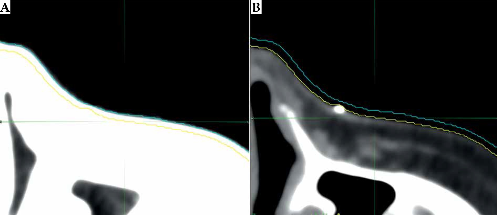
The initial CT scan is commonly used to model patient anatomy as a starting point to design the mould. The slice thickness, an in-plane resolution, has implications for the smoothness of applicator and, subsequently, the fit to patient’s unique anatomy. Modern computed tomography systems are capable of 0.5 mm spatial resolution in each plane [67]. But even with sub-millimeter resolution, other difficulties present themselves. Window and levelling often change the perceived edge of the skin surface. Determination of the true surface of patient can be subjective, and window/level modifications can change the perceived surface by 1-2 mm, as demonstrated in Figure 2. Fusing MR or US with CT images can be performed to improve image clarity, but achieving an accurate fusion near the skin surface is difficult [6]. Additionally, image artefacts, which are especially common from the presence of fiducial wires on the skin, can further distort the surface. The standard CT-based workflow involves a CT scan to help design the applicator, followed by a subsequent scan after the applicator has been printed to verify the fit and planning.
Fig. 2
The effect of window/level adjustments on determining the extent of skin on CT images. The outer blue line is the outline of skin surface using a lung window/level (A), while the inner yellow line is the outline of skin surface using a soft tissue window/level (B). This figure is composed of original images
3D surface scanning
Where available, the simulation CT scan has been replaced in favor of a quicker surface scan technique. These non-ionizing surface scans offer an alternative to reduce dose to the patient and improve workflow efficiencies [32, 53]. There are 3D surface scanning technologies that can obtain surface topology from handheld devices. A process for AM applicator creation from an optical scanning device was proposed as early as 2006 by Schreiber et al. [51]. Surface scanning devices are becoming more common in medicine [68]. In radiation therapy, they have emerged as an inexpensive and efficient way to acquire an accurate surface scan in less than a minute [69]. Types of scanners that are feasible for topology acquisition in superficial BT are based on structured light 3D scanning, which measures distances by assessing the reflections of light or infrared rays. Photogrammetry, a similar technique for gaining topological information, has been shown to be a feasible option as well. Photogrammetry uses many photographs from multiple angles to distinguish distances between many points on the images. Douglass et al. implemented it in the design of a AM superficial applicator, and noted that the scan was within 0.1% and 2.6%, when compared to CT scan values for volume and surface area, respectively [53].
There are some minor drawbacks to using a surface scanner. They can only provide topological information where they have a direct line of sight, and therefore cannot accurately operate within skin folds. Additionally, thick hair may be incorrectly assessed as a surface [70]. For some scanners, the distance that the object is scanned may affect the quality of the scan itself. Sharma et al. overcame this by creating a custom scanning gantry to consistently obtain the optimal scanning range for peak image quality and accuracy [69]. Overall, there are few disadvantages to surface scanning instead of CT imaging to acquire topological data for print design; however, after the applicator has been constructed, it is still advisable to conduct a planning CT to verify the fit.
Surface alginate impressions
For some sites, like the finger or penis, scanning technologies alone can be inadequate in providing accurate contour information. For these cases, negative impressions of the site can be obtained using alginate, from which a positive cast can be formed, laser scanned, virtually augmented with catheter lumen, and finally printed as a different material [32]. Moreover, this process eliminates the need for an initial CT scan.
Digital processing of patient’s data
Digital processing converts the raw images into a 3D model, which can be smoothed and modified to remove artefacts. The area of treatment is then delineated, and catheters’ tracks are plotted through a designed applicator object. Several software types may be required to perform all these tasks. To start, the initial image is processed and stored as a 3D model, notably a ‘mesh’. MeshLab and Blender, among others, are open-source computer-aided design (CAD) and modeling software capable of processing meshes. The actual standard file type for 3D models in AM is STL, that which was used for the original stereolithography files in 1986. Nowadays, that all AM technologies are capable of using this file type, the component terms of standard tessellation language or standard triangle language have been retroactively applied to the STL acronym [71]. Other common file types include OBJ, AMF, and 3MF [72]. With DICOM files, open-source software, such 3D Slicer, has modules to design printable objects within the scan. After a design is specified, the models are then converted into G-code, a set of print instructions ranging from infill percentage to slice thickness, by the appropriate slicing software. Specialized medical software from vendors, such as MIM Software Inc. (Cleveland, Ohio, USA) and Adaptiiv Medical Technologies Inc. (Halifax, Nova Scotia, Canada) can integrate directly with commercial treatment planning systems for digital processing and conversion to print-compatible file types. Table 1 lists the software noted in recent publications in AM for superficial BT [30-46, 48, 51-53, 55-57, 73, 74].
Table 2
Dosimetric testing of additive manufacturing (AM) applicators for 192Ir superficial BT
| Author(s) [Ref.] | AM material(s) | Dosimeter | Analysis tool | Comparison material | Results | Notes |
|---|---|---|---|---|---|---|
| Bassi et al. [38] | Cheetah (NinjaTek, USA) | GafChromic film EBT3 (Ashland Inc., USA) | PDD – point comparisons | Water | Comparing results along 7-30 mm with and without the material present, the average and maximum percent depth dose differences were 2.2% and 4.7%, respectively | The material was found to be water-equivalent at 192Ir energies and in agreement with TPS calculations |
| Cunha et al. [40] | PC-ISO (Stratasys, Inc., USA) | GafChromic film EBT2 (International Speciality Products, now Ashland Inc., USA) | PDD – point comparisons; HU – point comparisons | Water | PC-ISO is comparable to water, based on < 1% difference in measurements on PDD between 1-6 cm. The mean HU values were –10 and –1 for the material and water, respectively | Small HU value difference with water may be linked to internal honeycomb pattern. Note: this study does not involve superficial BT directly but it does test the material used in [51] |
| Harris et al. [41] | ABS (BitsFromBytes, UK) | GafChromic film EBT3 (Ashland Inc., USA) | PDD – point comparisons | Water | From 1-3 cm and 3-5 cm distance from source, ABS had ~1% and ~0.5% lower doses, respectively, when compared to water | A thorough analysis of the physical material and print properties was also completed |
| Oare et al. [39] | ABS1, PLA1 | GafChromic film EBT3 (Ashland Inc., USA) | PDD – uncertainty analysis | Water | Doses in measured in both materials were within the expected uncertainty range | According to the authors, PLA and ABS can be used instead of water for 192Ir BT film calibration |
| Park et al. [42] | Dragon Skin 10 (Smooth-On Inc., USA), HIPS1 | GafChromic film EBT3 (Ashland Inc., USA) | PDD – Gamma analysis | Freiburg flap | The elastic Dragon Skin applicator showed the highest gamma passing rates when compared to the other materials | High passing rates for Dragon Skin likely due to the higher setup reproducibility of the elastic material compared to the others |
| Ricotti et al. [43] | ABS1 | GafChromic film EBT3 (Ashland Inc., USA) | PDD – Gamma analysis | Freiburg flap | No significant dose distribution variations found between the ABS test parts and the Freiburg flap | Various infill percentages and geometries were tested |
| Wiebe et al. [44] | Accura ClearVue (Stratasys, Inc., USA) | InLight nanoDot Dosimeter (Landauer Inc., USA) | Kerma – point comparisons | Water | The total relative air Kerma detected through water, even though the material was the same | This study does not involve superficial BT directly but it does test the material used in [32] |
Within the digital design process, several practical considerations would dictate catheter placement within the mould for the target volume. The orientation of the source paths should be limited to avoid travelling over or near organs at risk (OARs; such as the eye). Access to the after-loader may also influence the direction of the connector end of the catheters to avoid the transfer tube resting on the patient. Lumen path curvature should be designed in a way that follows the minimum radius of curvature specification of the remote afterloader. The source paths are generally forward-planned, based on the expertise of radiation oncologist, medical physicist, or brachytherapist. Several groups have developed computer algorithms to optimize BT catheter paths as well as dwell positions, in the hope of eliminating the need for human oversight [75-77]. To date, however, inverse optimization of catheter paths have not been implemented for superficial BT.
Physical printing
Once the STL file has been generated, a selection of printer types must be made. For skin BT, the two dominant AM device technologies are FFF/FDM and SLA. These can be differentiated based on the achievable resolution of the printed products. In general, FFF/FDM printers can achieve resolutions on the order of 178-330 µm, while SLA printers typically achieve 50-125 µm [65]. SLA printed applicators are often smoother and more accurate than FFF/FDM techniques [78]. The amount of material chosen to fill the object, known as ‘infill percentage’, will affect fabrication speed and can have a limited effect on the dosimetric property of the applicator as well [43]. Most AM technologies, however, are rapidly improving, and achievable resolutions and fabrication speed continue to increase.
Printing skin BT applicators is still mostly a manual design and verification process with limited vendor support. A typical workflow of superficial BT in AM is shown in Figure 3. As the field evolves, the hope is that a treatment planning system will offer a method to create STL files or AM applicators directly from the planned treatment; thereby, further reducing the discrepancy between the predicted and delivered dose distributions. Currently, the design of AM applicators is still based on experience; though, this is now performed digitally – inverse anatomy-based optimization of the mould and lumens is presently unavailable for skin BT.
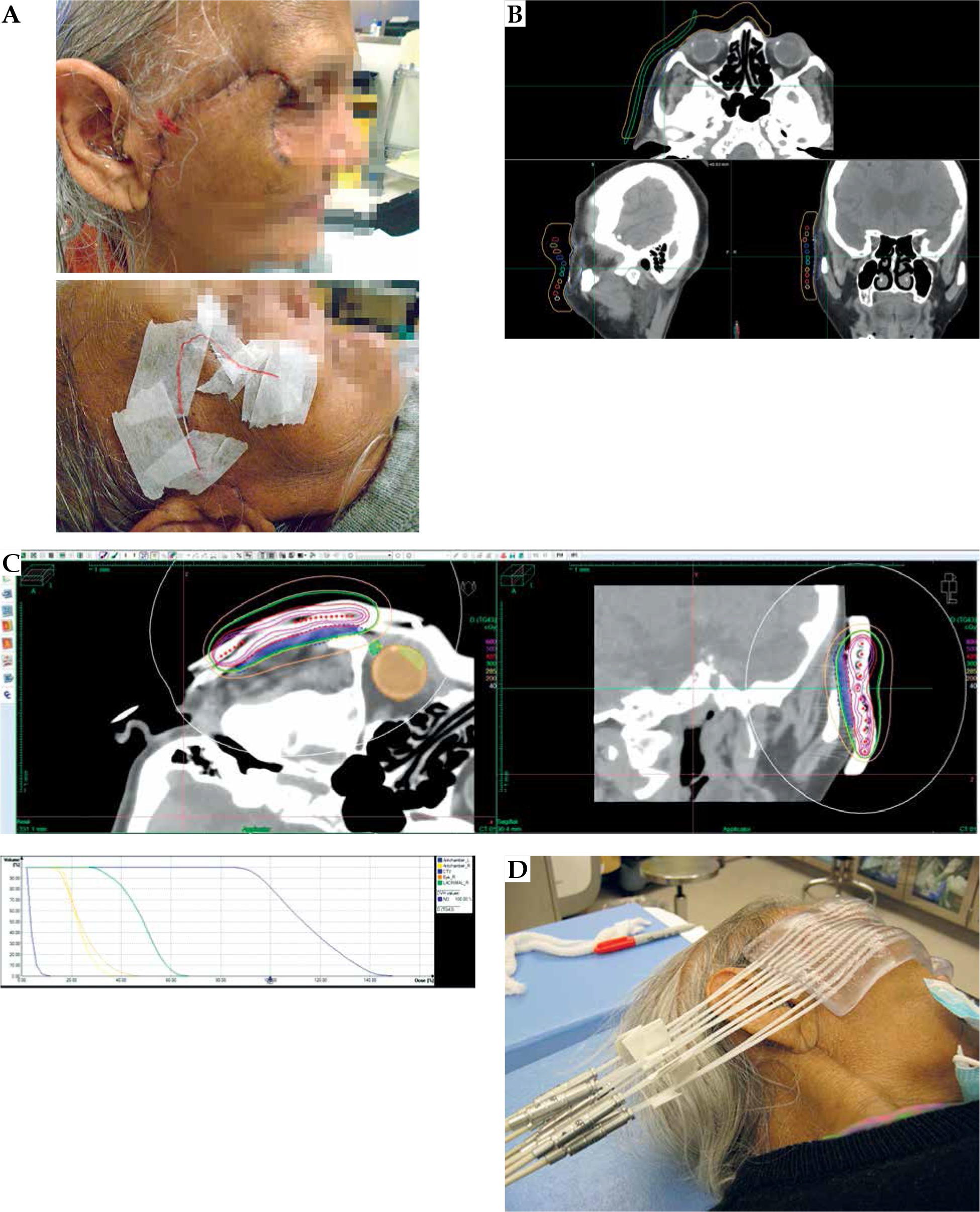
Fig. 3
An overview of the superficial brachytherapy process in additive manufacturing (AM). A) The surgical scar of the treatment area is lined with a fiducial wire. B) The patient is given a pre-planning CT scan. The applicator is digitally designed over the delineated clinical target volume (CTV; in blue) in MIM TPS (MIM Software Inc., USA), and the catheters’ channels (in multi-color) are manually placed in Oncentra TPS (Elekta, Sweden). C) The applicator is printed and placed on the patient for the planning CT. MIM TPS was used to define the target and organs at risk. Oncentra Brachy TPS was used to create the treatment plan. The DVH highlights the wide range of doses across the CTV. D) Treatment with patient-specific AM applicator. Note: The applicator was manufactured by Agile Manufacturing Inc. (Uxbridge, Canada) using a stereolithography device and the Accura ClearVue material (3D Systems, Inc., USA). This figure is composed of original images
Quality assurance – materials and moulds
Materials
In radiation therapy AM, several polymer types have been used extensively. For FFF/FDM applicators, these materials include commercial variants of polycarbonate (PC), acrylonitrile butadiene styrene (ABS), thermoplastic polyurethane (TPU), polylactic acid (PLA), and high impact polystyrene (HIPS) [65]. For SLA applicators, there are several UV-activated photopolymers with various physical properties as well, although these are seen less frequently in radiation oncology applications, possibly due to printer and material costs. Material clarity can have an impact on usability of a skin brachytherapy applicator, as optically clear parts are easier to assess for flaws, contact with the skin, and accurate placement over the target lesion. Also, each material type has commercial variants that are certified for their biocompatibility and compatibility with sterilization.
Biocompatibility
Biocompatibility describes the interactions of biomedical devices with biological tissue. This testing is essential when novel medical devices are to be placed in or on the body. Additionally, the United States Pharmacopeia (USP) provides standards for in vivo materials biocompatibility testing and classification. The USP classifications range from class I to class VI, depending on the requirements for biological inertness; class I is approved for use primarily on the skin and can be potentially harmful if placed within the body, whereas class VI materials are approved for permanent deep-tissue applications. AM applicators that are intended for skin BT can be categorized as surface devices with limited contact duration (i.e., < 24 hours). Therefore, the USP material’s requirements for skin brachytherapy are at least class I for uncompromised skin contact devices. Note that USP classification testing is viewed by some as a minimum requirement for medical devices. The International Organization for Standardization (ISO) 1009-1 provides more comprehensive set of tests to consider in the evaluation of biocompatibility of medical devices [79]. As examples, materials, such as PC-ISO from Stratasys Ltd. (Eden Prairie, Minnesota, USA) and Accura ClearVue from 3D Systems Inc. (Rock Hill, South Carolina, USA) both have USP class VI approval, while PC-ISO is also ISO 10993-1 rated [80, 81]. Using non-certified plastics may still be feasible if a certified biocompatible coating is added, or as non-clinical tools [41]. Preventing harm to the patient through adverse materials interactions is only the first step in material’s selection.
Sterilization
The extent, to which a material can be decontaminated is another essential factor that impacts materials’ selection for medical devices. While commercial ISO-certified materials for AM may be listed as ‘sterilizable’, this refers to the raw materials and not necessarily the printed object. This is particularly problematic for BT applicators given their form, which include long lumens of varying curvature approximately 2 mm in diameter.
Unlike most BT procedures, superficial BT of intact-skin lesions using customized applicators for each patient does not need to be sterilized. A low-level disinfectant is recommended by the Centre for Disease Control (CDC) for sterilization of medical devices in contact with the skin [82]. For printed superficial BT applicators, this involves placing the AM applicator in a vat of an enzymatic cleaning agent, such as ortho-phthalaldehyde (OPA), a high-level disinfectant with good material compatibility [83], in between fractions. Care should be taken to ensure that the chemicals used would not affect the material or the integrity of the print. In instances where the applicator could meet breached or significantly compromised surfaces, sterilization of the applicator prior to use should be considered. For many common AM materials in medicine, hydrogen peroxide (HO) gas plasma is the recommended sterilization substance because of its high sterility rate and absence of mechanical damage to the print during the process [84]. In contrast, high heat sterilization, such as autoclaving, can warp a 3D print. Each print should be inspected thoroughly after sterilization.
Physical assessment
Independent verification of the dimensional accuracy of the printed applicators and the lumen are important, as they are often distorted from the digital model. Harris et al. observed that there was as much as a 0.8 mm difference between the planned and physical lumen sizes, and the reproducibility of the catheter placement within the lumen varied by 0.5 mm, on average. These variations were most pronounced at the lumen openings, so a viable option to reduce this source of variation would be to taper the lumens at these points [41]. Ensuring that catheters can pass freely through the lumen is also essential. Vendor-supported catheters should be inserted into the AM applicators and be the only material that encounters the source. The catheter tubing ensures that the source never contacts uncured material and never jeopardize the retraction of a stuck source. The geometry of the print should be assessed on the verification and planning CT scans, ensuring appropriate infill and internal structure integrity. Producing an acceptable print is highly related to parameter choice and printer calibration [46]. Still, imperfections or inaccuracies should be considered during the planning process.
Assessing dosimetric quality of materials
A primary consideration when using different materials as customized applicators is conducting proper dosimetric assessments of the material. For superficial BT purposes, applicator materials must be dosimetrically water-equivalent, possessing the same attenuation properties, given that TG-43 formalism assumes this property of tissues used in dose calculations [85]. A general method to test for water-equivalency has been proposed by Cunha et al. [40]. In addition to water-equivalency, treatment planning calculated doses through printed materials must match actual delivered doses. Water-equivalency and treatment planning dose comparisons can be checked using radiochromic film measurements. Several studies have reported on the dosimetric properties of various AM materials, specifically the dose fall-off over appropriate distances and through different material thicknesses [38-44]. In each study, the authors declared the tested material water-equivalent, possessing comparable properties to a water-equivalent material, or measured dose through the material equivalent to those predicted by the treatment planning system (TPS).
Other studies have reported on water-equivalency of materials using 192Ir energies, such as PC-ISO (Stratasys Ltd., Eden Prairie, Minnesota, USA) as well as non-certified PLA and ABS, with each material determined to be water-equivalent [39-41]. Dosimetric testing of ABS by Ricotti et al. has also been performed using varying amounts of infill percentage. Infill percentage is the extent, to which a 3D print’s internal portion is filled in, with less than 100% infill resulting in a honeycomb-like pattern of air gaps within the print. Ricotti et al. compared dose distributions among a commercial Freiburg flap, a replicated ABS flap printed with 10% infill and 3 parallelepipeds of the same thickness as the Freiburg flap, with 10%, 20%, and 40% infills. The dose distribution of each AM applicator was in agreement with the commercial flap, showing that partially hollow low-cost material applicators do not adversely affect dose distributions [43]. Common AM applicator materials, even inexpensive ones, offer water-equivalent attenuation properties. The results of dosimetric testing methods on various materials using 192Ir sources and Gafchromic film (Ashland Inc., USA) are summarized in Table 2. Furthermore, material heterogeneities have been shown to be negligible for source distances less than 10 cm when using 192Ir [86].
Treatment planning
The goal of the treatment planning process is to cover the target volume while sparing adjacent OARs and maintaining uniformity throughout the target volume. In general, in superficial skin BT, the dose is prescribed to 3-5 mm under the skin surface and the source is preferably placed 5 mm from the surface to avoid overdosing skin surface [10]. To date, there are ranges of prescription patterns in superficial BT, depending on the disease extent and selected applicator type. The American Brachytherapy Society recommends a dose between 40 Gy/10 fractions and 42 Gy/6 fractions [6]. Based on the literature and experts’ opinion, a rough guide for treating lesions with a thickness of 3 mm is to place the catheters 3-5 mm from the surface. In cases where a sharper dose fall-off is required near adjacent OARs, a smaller offset for the catheters should be considered. Conversely, to treat at a greater depth, keeping the source away from the skin’s surface may be beneficial. Such technique is used in Manchester skin BT method, in which individual mould or flap is placed over additional bolus of various thickness, pending clinical need [87]. Of course, tailoring the source distances across the skin is possible with a customized AM applicator. For commercial devices, such as the Freiburg flap, however, that distance to the surface remains fixed at 5 mm and the proximity to neighboring catheters is set at 10 mm, limiting the amount of modulation available to treat complex surfaces. The American Brachytherapy Society provides some guidance on planning objectives, specifically in terms of hot spots on the skin surface, where they recommend that the dose should be limited to 125% for larger lesions treated by flaps and to 140% for smaller lesions considered custom moulds [6]. Treating skin lesions with superficial BT to a thickness beyond 5 mm is not recommended due to unacceptably high surface doses [6], although some centers would consider such method in lesions with thickness above 5 mm [88].
Treatment and case studies
Table 3 summarizes the case studies to date that are directly related to AM in superficial BT. In fitting with the appropriateness of using superficial BT to treat irregular topologies, noses are the most prevalent types treated with AM applicators according to various clinical research publications. One author noted that reproducibility of setup was actually better with an irregular topology and an AM applicator due to inherent indexing of the applicator on the anatomy and less risk of mispositioning compared to a flat surface [38]. Lecornu et al. identified that to facilitate placement on facial sites, constructs that would enable elastics loops for around the ears or head are useful in applicator’s design [33].
Table 3
Published cases of additive manufacturing (AM) in skin brachytherapy
| Author(s) [Ref.] | Site | Disease | No. of patients | Dose (Gy/fx.) | Rx depth (mm) | Surface dose (Gy) | Shielding |
|---|---|---|---|---|---|---|---|
| Aldridge et al. [37] | Finger | – | 1 | – | – | – | – |
| Casey et al. [31] | Left shin | BCC | 1 | 40/10 (q.a.d.) | 5 | – | N.A. |
| Clarke [30] | Nose | BCC | 1 | 55/20 | – | – | Eyes |
| D’Alimonte et al. [32] | Penis | SCC | 5 | 40/10 | 5 | 44-65 | N.A. |
| Jones et al. [34] | Nose | – | – | – | – | – | Eyes |
| Lecornu et al. [33] | Nose | BCC & SCC | 2 | 36/6 | – | 51.6, 48 | Eyes |
| Taggar et al. [35] | Fingers (5) | Psoriasis | 1 | 16/12 | 2 | 21.6 | Hand |
| Voros et al. [36] | Penis | SCC | 5 | 40/10 (b.i.d.) | – | – | N.A. |
Economics and institutional risk considerations
Implementation costs are a major factor when considering AM technologies in radiation oncology. In one superficial BT study, AM applicators were shown to be less expensive and more efficient than manual applicator fabrication techniques [57]. Materials and equipment come in a range of qualities and costs. Lecornu et al. purchased a printer for a fixed cost of 5,000 Euros, and incremental costs of 10 Euros for each applicator [33]. Conversely, Harris et al. proved that lower cost printers (< 500 US$) and materials can be employed effectively for accurate AM applicator creation; however, biocompatibility and sterility of the non-certified materials were not considered in this study [41]. AM produces applicators that are more consistent and take less time than manual applicator construction [54]. In one study, the manual labor hours required for AM compared to manual methods were 6.25 hours and 9.50 hours, respectively [57]. Still, many barriers exist to prevent the implementation of AM workflows within the clinic. Time to implement, staff training, and expertise required to achieve consistently accurate results are the barriers to more widespread use of AM techniques in radiation oncology [58]. For some centers, these concerns combined with patient’s volume considerations and the initial cost outlay for the printing hardware raises the question of outsourcing the process. Outsourcing the printing and leveraging the skills and superior equipment of a specialized AM provider may prove most economical, if the required number of prints each year is relatively low. Researchers in [32], [35], and [44] from the Sunnybrook Health Sciences Centre relied on an external company to create higher quality SLA applicators after designing them in-house. Still, this expertise would come at a premium, as noted by Lancellotta et al. [89].
Every institution has risk mitigation programs often prescribed via their insurance providers, which would impose restrictions on the AM skin BT program. It is imperative before beginning an AM skin BT program that institutional consents for producing medical equipment internally are fully approved and supported. Outsourcing or having processes in place for printed moulds for irregular surfaces as well as re-usable, standard moulds for flat skin surfaces are also worth considering [57].
Conclusions
Additive manufacturing applicators are attractive alternatives to standard superficial BT approaches. AM applicators enable the treatment of skin BT sites that would otherwise pose challenging for conventional methods. They have the main advantage of tailoring the applicator to be individualized to a patient’s unique anatomy. Furthermore, AM applicators have the potential to improve the accuracy of treatments, while simplifying the process to create the applicators. However, with the implementation of any new technology, a rigorous quality assurance program should be developed alongside the clinical program.


