
Purpose
High-dose-rate (HDR) intracavitary brachytherapy (ICBT) provides a high radiation dose to the tumor and a low radiation dose (exposure) to surrounding normal cells/organs at risk (OARs) [1, 2]. This makes it an essential component of definitive radiotherapy treatment for cervical cancer [3-5]. Radiation sources, such as cobalt-60 (60Co) and iridium-192 (192Ir) are commonly used in clinical practice. In low- and middle-income (LMIC) countries, 60Co is often preferred over 192Ir due to its economic and logistical advantages, primarily stemming from its longer half-life of 5.27 years compared with 74 days of 192Ir [6-8].
Despite its importance in definitive radiotherapy for cervical cancer, inappropriate administration in ICBT can lead to either an underdose of the tumor, which impairs tumor control, or an overdose of OARs, such as the bladder and rectum, which may cause radiation-induced damage in patients [2, 9]. In vivo dosimetry (IVD) is a practical tool/procedure to help detect errors (uncertainties) emerging during intracavitary brachytherapy, which may cause radiation-induced effects in patients.
In vivo dosimetry measures radiation dose at an organ of interest during radiotherapy [10, 11]. It assesses the amount of radiation administered at the location or volume of an organ using a radiation detector [9, 11]. This helps to detect and reduce radiation treatment inconsistencies, which could lead to a loss of tumor control or radiation damage [12, 13]. Therefore, IVD can be utilized to determine if the radiation damage seen in patient’s post-radiation treatment are caused by intracavitary brachytherapy or other unidentified variables. To determine uncertainties in brachytherapy treatment, IVD can be performed using different radiation detector systems, such as optically stimulated dosimeter (OSD) [14], semiconductor diode [15, 16], metal-oxide-semiconductor field-effect transistor (MOSFET) [9, 17], thermoluminescent dosimeter (TLD) [18, 19], inorganic scintillation detector [20], and plastic scintillation detector [21].
Numerous authors [22-25] have examined and demonstrated the usefulness of LiF: Mg, Ti (TLD-100) by simulating its adequate small size to detect doses in high-gradient regions, linear dose response, and tissue-equivalent effective atomic number (8.2 for TLD-100 vs. 7.4 for tissue) [24], which make it suitable for in vivo dosimetry in brachytherapy and radiotherapy in general. However, it has some disadvantages, including the challenge of localizing their position in patients during dose measurement as well as being a passive detector [12, 26]. Magnetic resonance image-guided adaptive brachytherapy (MR-IGABT) is currently the gold standard for brachytherapy globally [27], but only few centers in low- and middle-income countries (LMIC), particularly in Africa, are switching into 3D CT-based brachytherapy. Though the EMBRACE study considers CT-based brachytherapy to be of limited use in the assessment of boundaries of the tumor against normal cervix and uterus [28], majority of LMICs are still using 2D orthogonal image-based planning. 2D intracavitary brachytherapy has been the subject of numerous studies [1, 2, 29] in developed countries, and various setups, which have been proposed in these studies to enhance 2D HDR-ICBT are currently employed by centers still using 2D-based brachytherapy. However, some recommendations are not implemented owing to a variety of factors, including inadequate knowledge and skills, financial constraints, and shortage of human resources. For instance, the International Atomic Energy Agency (IAEA) [11] and the American Brachytherapy Society (ABS) [1] recommend that each ICBT fraction should be imaged and planned separately, and in vivo dosimetry conducted, but this becomes difficult to implement in a clinical setup due to numerous factors, some of which were already mentioned above.
Nevertheless, there is still an opportunity to perform studies in this field to improve 2D-based treatment in a hospital setup, because there are few studies on in vivo dosimetry in brachytherapy conducted in LMICs, where clinical systems may differ from the earlier studies performed in developed countries.
In the current study, rectum radiation doses were evaluated using TLDs in vivo dosimetry, and differences between measured dose by TLDs and planned dose by treatment planning system (TPS) were compared regarding treatment planning criteria for HDR brachytherapy fraction in 2D orthogonal-based image planning.
Material and methods
The study included 31 cervical cancer patients treated with orthogonal-based images intracavitary brachytherapy at the Bugando Medical Centre (BMC) between June 2024 and August 2024. Prior to brachytherapy, each patient received two fields (parallel-opposed and anterior-posterior fields) teletherapy treatment delivered with a 60Co unit (Bhabhatron II, Panacea Medical Technologies). Patients were administered 50 Gy in 25 fractions, with 2 Gy per fraction and 5 fractions per week, either with or without concurrent cisplatin-based chemotherapy, once a week. Using an HDR 60Co brachytherapy unit (SagiNova, BEBIG Medical GmbH), each patient was prescribed to receive a total of 24 Gy in 3 fractions, with 8 Gy per fraction, once a week, for three weeks consecutively. All brachytherapy treatments began after the completion of external beam radiotherapy treatment (EBRT), and the total treatment duration for both EBRT and ICBT was 8 weeks.
A radiation oncologist chose appropriate metal tandem and ring applicators (BEBIG Medical GmbH) for every patient during applicator insertion procedure performed under general anesthesia. The same applicators were utilized for all three fractions. A Foley catheter was inserted in the bladder, and a 7 ml solution comprising 6 ml of normal saline and 1 ml of iodine-based contrast (Omnipaque 350 Mg) was added. Following the insertion of the chosen applicators into the patient’s uterine cervix through the vagina, rectal probe containing TLDs and covered with the middle finger of sterile glove was placed into the patient’s rectum. Vaginal packing then started using gauze soaked in a solution containing 1 : 5 volume ratio of iodine-based disinfectant (Povidone) and normal saline. To prevent slippage, the applicator was mounted on a base plate (LAZ 22-01, BEBIG Medical GmbH), and the rectal probe was attached to the applicator after completing the insertion.
Imaging procedure
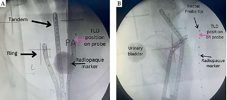
After insertion, orthogonal radiographic images (postero-anterior and lateral) were taken using a C-arm X-ray machine (Siemens, model 08888302) to depict the geometric location of the applicator and probe in the patient’s pelvis. Radiopaque markers were placed near TLD within a probe to verify its position after imaging, as shown in Figure 1. A reconstruction box (LAZ11-04, BEBIG Medical GmbH) was used to aid in determining magnification factor of the image. Subsequently, images were sent to treatment planning system (TPS) while the patient was shifted from brachytherapy couch to a hospital stretcher for treatment delivery.
Treatment planning and delivery
A SagiPlan software version 2.0.2 (BEBIG Medical GmbH) was utilized to reconstruct the applicators according to orthogonal images, establish dwelling points, and calculate dwelling time to produce a pear-shaped dose distribution according to the International Commission on Radiological Unit (ICRU) 38 recommendation [30]. The dose was prescribed to point A according to the Manchester system [30]. Three points at each of the urinary bladder and rectum points were established to represent urinary bladder and rectum doses as recommended by ICRU 38 [30], and five points in the rectal probe with TLDs were used to predict planned dose to TLDs at anterior points in the rectum. After completion of treatment planning, the plan was sent to treatment delivery unit (SagiNova, BEBIG Medical GmbH) using a 60Co source (Co0.A86) [31], ready for intracavitary HDR treatment administration according to the plan.
Rectal probe and TLD reading
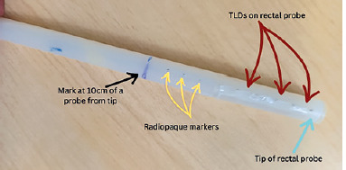
A rectal probe was made from a plastic flexible tube taken from an old malfunctioning surgical aspirator tube (Elmaslar SA 01 HT) with the following dimensions: 1.5 cm diameter (outer to outer) and 15 cm length. Ten radiopaque ball bearings, each made of soldering wire with a diameter of about 1 mm, were placed 10 cm from the tip of rectal probe, and spaced 1 cm apart, as illustrated in Figure 2. This allowed locating TLDs position on the rectal probe during radiographic imaging and treatment planning. TLDs on the probe were placed in between two radiopaque materials: 5 TLD rods (Harshaw, LiF: Mg, Ti) with a diameter of 1 mm and a length of 6 mm each, spaced roughly 1 cm from center to center from one another. After that, TLD was secured using adhesive tape. A thin plastic sheet was positioned in between to prevent TLD contamination.
Following the administration of treatment, the patient’s probe was taken out and TLDs were removed from the rectal probe. They were then placed in a light-sealed container according to allocation number, and sent to Tanzania Atomic Energy Commission (TAEC) for analysis. Reader parameter setting utilized during TLD rods reading were as follows: pre-heated at 50°C temperature, time 0 seconds, acquisition maximum temperature of 300°C, time 33.33 seconds at a rate of 10°C per second, and annealing temperature of 300°C, time 0 second. These TLDs were read using a hot gas chamber in a TLD reader (Harshaw 4500, USA). TLD rod was positioned at slot 1 of TLD card above Teflon cover (Harshaw card).
Prior to patient measurement, the TLD reader and TLD rods were calibrated in secondary standard dosimetry laboratory (SSDL) at TAEC, and phantom was irradiated at BMC in accordance with the manufacturer’s instruction and the International Atomic Energy Agency’s (IAEA) Human Health series 8 of 2013. Cobalt-60 sources were applied for TLDs calibration; at SSDL, a dose of 1 mGy was used, while at BMC, a dose ranging from 1 Gy to 8 Gy was employed for phantom irradiation. Table 1 displays the experimental uncertainties observed during calibrations.
Table 1
Thermoluminescent in vivo dosimetry uncertainties
Patient cluster
Based on treatment planning criteria, there were two patient groups: 18 patients in the first group received treatment with first fraction planning (FFP), which was used to treat all three fractions, and 13 patients in the second group, each of whom received treatment using separately planned fraction (EFP), as advised by the American Brachytherapy Society (ABS). In all patients, only two fractions were involved for in vivo dosimetry.
Ethical clearance
The Catholic University of Health and Allied Sciences, Bugando Medical Centre Research, and Ethical Committee (CREC) approved the ethical clearance, with approval number of CREC/779/2024.
Statistical analysis
Data were tested for normality using Shapiro-Wilk test. For normally distributed data, statistical significance was determined with t test, while for non-normally distributed data, Wilcoxon test was employed. A p-value < 0.005 was established as threshold for rejecting the null hypothesis. Data analysis was conducted using R version 4.4.1 and SPSS version 27.
Results
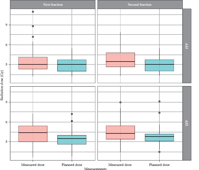
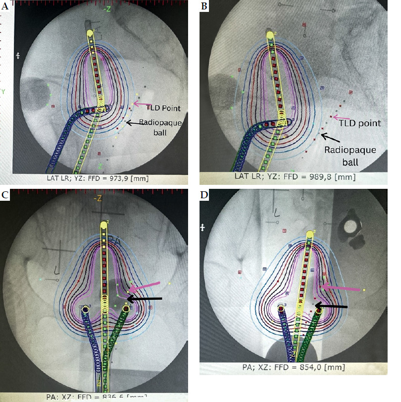
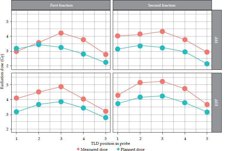
The observed patients, who attended brachytherapy treatment at the BMC, had a mean age of 52 ±2.5 years, ranging from 30 to 83 years, and FIGO disease stage of IB to IIIC. Most (90.3%) were non-insured patients, while only 9.7% were insured patients. 83.9% of the patients were prescribed to receive concurrent chemo-radiotherapy, followed by intracavitary brachytherapy, and 16.1% received only radiotherapy due to underlining factors, such as older age and renal failure. In this study, a total of 302 observation points were initially collected for in vivo dosimetry using TLDs. However, 19 observation points were excluded from the analysis due to quality control measures. These exclusions were based on TLD points planning and readings, which were either exceptionally low or high, indicating potential measurement errors or missing one observation data, either planned or measured at a point. As a result, 283 valid observation points were retained for final analysis, ensuring integrity and accuracy of dosimetric data. Dose differences between those measured by TLDs and those planned by TPS were observed: 91 (32.2%) points had low measured doses compared with planned doses, 190 (67.1%) points had higher measured doses, and 2 (0.7%) had equal doses between measured by TLDs and planned by TPS. Whisker and box plot (Figure 3) summarizes the observations. The overall planned mean dose to the rectum (3.27 ±1.16 Gy) was less compared with the measured mean doses (3.99 ±1.63 Gy), and this was statistically significantly different (p-value < 0.001). Table 2 provides the details. Applicators compared with rectal probes demonstrated a minimal change between fractions (Figure 4). The mean position shifts between first and second fractions for the applicator and probe geometric coordinates provided by TPS as well as the means of dose differences between second and first fractions, either planned or measured, are displayed in Table 3. As indicated in Table 4, the second fraction of FFP had a higher mean dose difference (0.87 ±1.89 Gy), but not statistically different from the first fraction’s mean dose difference (p = 0.189). This was in contrast with other fractions, which involved imaging and planning. TLDs at position 3 (the middle of rectal probe containing TLDs) had larger mean doses than TLDs at other places of the rectal probe for all fractions, whether they were FFP or EFP, according to the observed mean dose differences based on TLD location in the rectal probe (Figure 5). Due to its proximity to the radiation source, this rectal probe point location complied with the ICRU 38 rectal point recommendation, which was anticipated to have a larger rectal absorbed dose than at other locations.
Table 2
Mean doses planned by treatment planning system (TPS) and measured by thermoluminescent dosimeter (TLD) in intracavitary brachytherapy at the Bugando Medical Centre
Table 3
Mean differences in activated points in applicator and probe shift between first and second fraction, and corresponding mean dose differences for planned and measured doses in patient’s rectum
Table 4
Mean dose differences according to planning criteria and brachytherapy treatment fractions
Discussion
High-dose-rate intracavitary brachytherapy is an essential component of definitive radiotherapy treatment for cervical cancer. However, inappropriate administration can lead to either an underdose of tumors or an overdose of OARs, such as the rectum, which can result in radiation-induced toxicity. In this study, the measured mean dose to the patients’ rectum using TLDs was higher than the TPS-planned mean dose. Although the higher mean dose difference in the second fraction of FFP was not statistically significant compared with the first fraction (p = 0.189), it still raises concerns. Similar findings have been reported in previous studies [32-34], and despite using 3D CT-based planning, these studies also observed no statistically significant differences between first fraction-based planning and each fraction separately planned.
Jamalludin et al. [9] used Moskin MOSFET and diode for in vivo dosimetry using 60Co source, and found that the mean measured dose for both detectors was less than the planned dose by TPS. Zaman et al. [16] utilized a diode with 192Ir source, and observed that the planned dose was higher than the measured dose. Similarly, Kessaris and Nori [19] employed TLD with 60Co source, and reported the measured dose to be less than the planned dose. In the current study, the measured mean dose (3.99 ±1.63 Gy) was slightly higher than the planned mean dose (3.27 ±1.16 Gy), which was statistically significantly different (p < 0.001), as shown in Table 2. Singh et al. [17] with MOSFET detector and Oyekunle et al. [18] using TLDs with 60Co source, noted similar findings, where the measured dose was higher than the TPS-planned dose.
Several factors could explain the differences between planned and measured doses, including the movement of TLD rods closer to radiation sources during treatment compared with the image acquisition time, slight discrepancies between the planned and actual TLD position within patient, and shift in applicator’s placement due to patient’s movement. Moreover, tumor response or shrinkage due to treatment could influence TLD measurements, especially throughout multiple fractions. As the tumor shrinks, it may alter the radiation dose distribution, potentially increasing the dose to nearby tissues or OARs, which could lead to variations in the measured doses. Other contributing factors include the positional shift of the rectal probe due to slippage within the rectum (despite fixation), rectal shifts between imaging and treatment, the absence of degassing procedures during brachytherapy, applicator’s movement due to patient re-positioning from the brachytherapy couch to a stretcher, difference in technique and expertise among radiation oncologists during insertion and parking as well as variation in medical physicist planning, could further impact dose accuracy. Additionally, patient’s movements during sedation recovery when using general anesthesia may also influence dose measurement [4, 9, 18, 35].
The higher means on both planned and measured doses at TLDs positioned in the middle of the rectal probe (position 3) correlate with the ICRU 38 rectal point, located in the area of high brachytherapy radiation gradient, as it is closer to the radiation source during two dimension-based (2D) brachytherapy. This observation is supported by several studies [9, 18, 19, 36]. Points further from the middle of the probe received lower mean radiation doses due to the inverse square law, where the dose decreased with the square of the distance from the radiation source.
The slight difference in planned dose between the first and second fractions in FFP, despite using the same planning, could be attributed to adjustments made in dose distribution by medical physicists to improve the plan. In the other group, the expected differences in the mean planned doses were due to changes in applicator and probe positions during brachytherapy interfraction.
While the TLD dose in a rectal probe based on point dose planning may not be a perfect representation of rectum doses [12], the higher measured doses compared with planned doses are alarming, and warrant further investigation of radiation doses and radiation-induced toxicity to OARs in these patients. The observed significant differences between the measured and planned doses can be attributed to the shifting of patients from the brachytherapy couch to a hospital’s stretcher, which resulted in a displacements of applicator positions. Therefore, it is recommended to further investigate the impact of patient’s movement on dose discrepancies.
This study have several limitations. First, TLD position was initially verified using radiographic images for planning, but TLDs were not re-verified during treatment, which introduce uncertainty regarding their exact position during dose delivery. Second, positioning uncertainties may arise from factors, such as patient’s movement, applicator’s shift, and anatomical organs’ movement within a fraction or between fractions. While the rectal probe was securely fixed to minimize these uncertainties, positioning accuracy remains a limitation of the study. To mitigate this concern in future studies, real-time imaging or verification during treatment can be utilized to enhance the accuracy of dose measurements. Another limitation of the IVD system in this study was the reading interval of around two weeks, resulting measurements from previous fraction not readily available for immediate dose corrections in subsequent fraction. To address this issue, alternatives, such as integrating real-time dosimetry systems, e.g., MOSFET or diode, could offer continuous dose monitoring. Additionally, modifications to the flow of TLDs reading, including faster reading techniques or utilization of more timely feedback mechanism, e.g., in-house reader, could improve the system’s applicability for read-time dose corrections.
Conclusions
No statistical difference was observed in the mean dose differences for both fractions when comparing FFP and EFP. However, the mean dose difference was higher in the second fraction based on FFP, indicating that relying on the first fraction planning for subsequent fraction dose delivery results in a higher dose to organ at risk (the rectum). Therefore, while it is generally best practice to plan each fraction independently, in cases where patients are shifted from a brachytherapy couch to a stretcher during procedures, separate imaging and planning for each fraction may not be necessary.


