
Purpose
Uveal melanoma is a tumor of the eye that has been commonly treated using either radioactive plaques or enucleation with comparable outcomes [1-4]. The use of specific gold alloy plaques loaded with radioactive iodine-125 (125I) seeds became standard after publication of the Collaborative Ocular Melanoma Study (COMS) [5]. The COMS trial showed that survival after 5 years is equivalent between plaque brachytherapy and enucleation for medium-sized uveal melanomas [6, 7], but the risk of impaired visual acuity after plaque brachytherapy is significant [8]. To avoid enucleation, in some cases, larger tumors than those included in the COMS study have begun to be treated with plaque brachytherapy [9, 10]. It has also been reported that under-dosing the margins of a tumor touching the optic disc leads to poor clinical outcomes [11].
Decreasing dose to critical structures in the eye while maintaining margin coverage, especially for tumors near the optic nerve, is a topic of clinical interest, and has been attempted in the past by techniques including modifying COMS plaques [12], using differently designed plaques [13, 14], and decreasing prescription doses [15-18]. Non-uniform loading to decrease dose to organs at risk (OARs) has been investigated with the use of COMS plaques [19], but due to significant dosimetric differences between COMS plaques and other plaque models, these results may not transfer to other types of eye plaques. The importance of correctly selecting the margin size and ensuring coverage of the margin has also been investigated, and the use of a more generous margin or prescribing beyond the tumor apex has been recommended to achieve better tumor coverage [20]. Although dose to sclera is rarely dose-limiting, increased radiation dose to tumor apex and to 5 mm depth is correlated with greater visual acuity loss, worse final visual acuity, and radiation complications [16]. Efforts to minimize the prescription depth past the tumor apex, and therefore minimize the radiation dose to 5 mm, while maintaining margin coverage, are worth considering.
Since the completion of COMS study, other 125I-based plaque models have gained popularity including Eye Physics (EP) (Eye Physics, LLC, Los Alamitos, CA, USA) models that use a gold alloy plaque with collimated slots, into which radioactive seeds are directly glued [13]. These plaques are commonly planned using Plaque Simulator (PS) (Eye Physics, LLC, Los Alamitos, CA, USA) treatment planning system (TPS) [21], and the plaques can be ordered from IsoAid, LLC (Port Richey, FL, USA) pre-loaded and pre-sterilized with IsoAid Advantage 125I (IAI-125A) seeds.
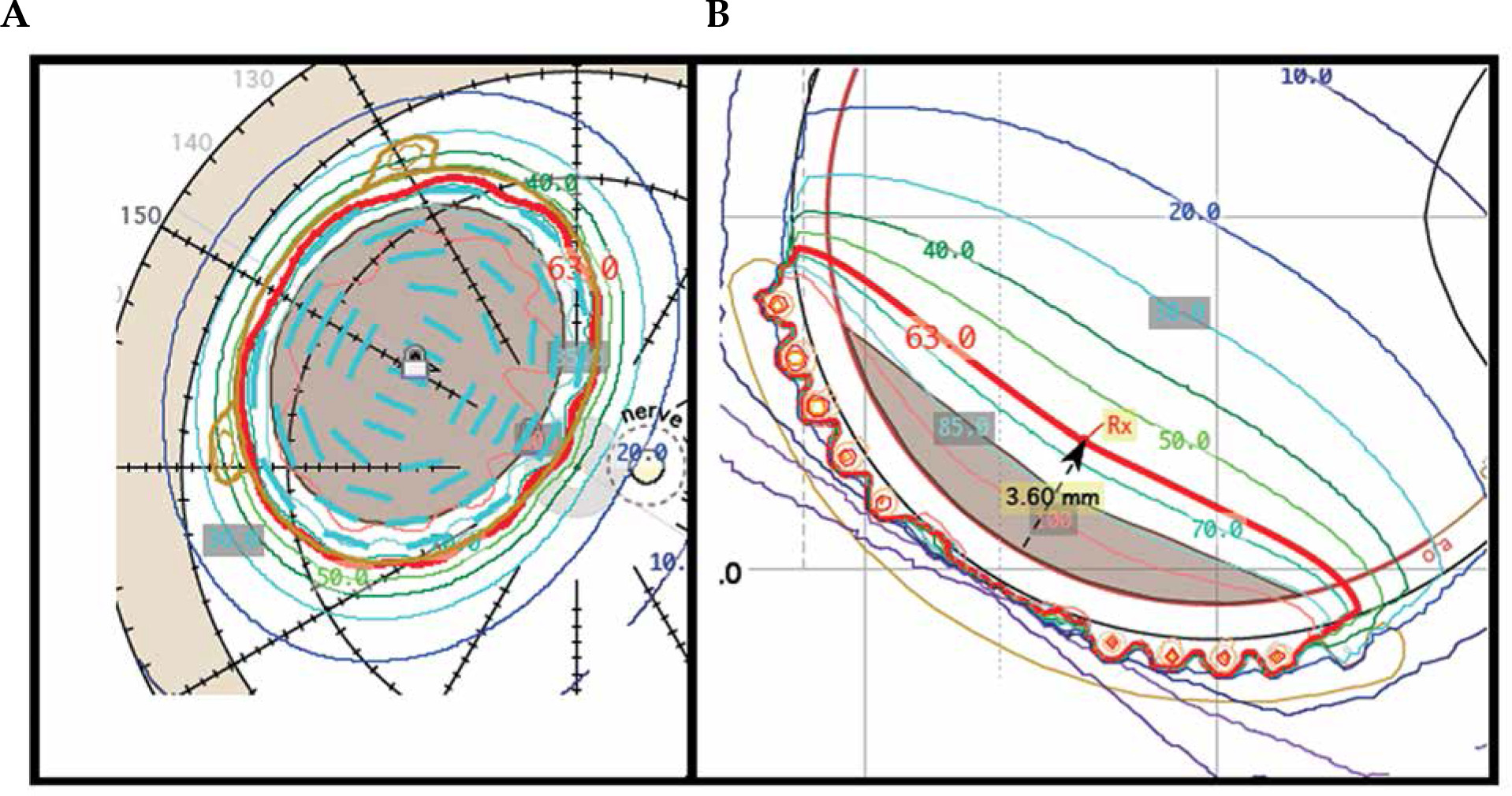
During clinical treatment planning, 2 mm margin is commonly used to ensure tumor coverage. If a 2 mm margin coverage cannot be achieved by prescribing to the tumor apex, one of two approaches is taken. First, a deeper planning apex height can be selected (e.g., 3.6 mm vs. 2.0 mm of tumor apex, Figure 1). Increasing the planning apex height will increase coverage of the margins of large shallow tumors as well as increase coverage of the portion of the margin located under the optic nerve, when tumors are close to the nerve. Alternatively, for tumors located away from the optic nerve, a plaque with a larger diameter can be used. Due to surgical considerations, including the location of the tumor, the ocular oncologist may request a specific size plaque to be used. It is our clinical procedure that if the planning apex is more than 2 mm deeper than the tumor apex, the plaque is sized up if a larger sized plaque is available.
Fig. 1
To obtain the base plus margin shown in (A), a planning apex of 3.6 mm was required as shown in (B). This planning apex is 1.6 mm deeper than the tumor apex of 2.0 mm
Currently in our clinic, uniform loading is used for eye plaque planning. This limits the flexibility of OARs sparing when there is an adjacent critical structure. Here, we investigated the feasibility of using dual radioactive 125I source strengths when loading plaques in certain clinical scenarios to either reduce the dose to critical structures in the eye including the inner sclera, disc center, and fovea, or improve surgical efficiency and patient’s comfort by using a smaller plaque.
Material and methods
Treatment planning in PS TPS
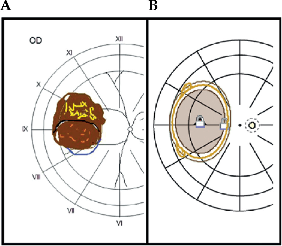
Clinical plans were based on azimuthal equidistant projection fundus diagrams and ellipsoidal approximations of tumor dimensions, provided by a single ocular oncologist. These approximations included a measurement of the base of tumor in both the radial (along a radial spoke from posterior pole) and circumferential (around the circumference of the eye) directions. The ocular oncologist also provided tumor apex height as determined clinically using ultrasound. These data were then transferred into PS TPS by the medical physicist. Figure 2 shows a side-by-side comparison of a representative fundus diagram, provided by the ocular oncologist, and the corresponding tumor digitization on the retinal diagram in PS TPS.
Fig. 2
Representative fundus diagram from the ocular oncologist (A) and its corresponding digitization within the PS TPS (B)
The goal was to cover a 2 mm margin on the basal dimension of the tumor and tumor apex, and achieve at least 95% tumor coverage, with the prescription dose of 63 Gy in 94 hours for a dose rate of 0.67 Gy/h. This de-escalated dose from the COMS standard of 85 Gy was based on published experience at Duke University, prescribing 70 Gy to the tumor apex using COMS plaques [16, 17]. This dose level was then further reduced for use with EP plaques due to radiation from EP plaques not being attenuated by a silastic insert, as it is in COMS plaques [22]. The standard COMS TG-43U calculations assume a homogenous water environment and do not account for a higher attenuation in the silastic material, and it has been shown that this can lead to a dose approximately 10% higher than calculated in a non-water attenuating material [23, 24]. Our initial clinical outcomes with 63 Gy prescription with EP plaques was recently published [18].
The dose calculation method used in PS was different from the traditional TG-43U [23] calculation used in the COMS trial in that it includes inhomogeneity corrections to account for the attenuation and fluorescence from gold backing as well as to correct for plaque specific collimation from the seed slots in EP plaques [25-27].
Three clinical scenarios of interest
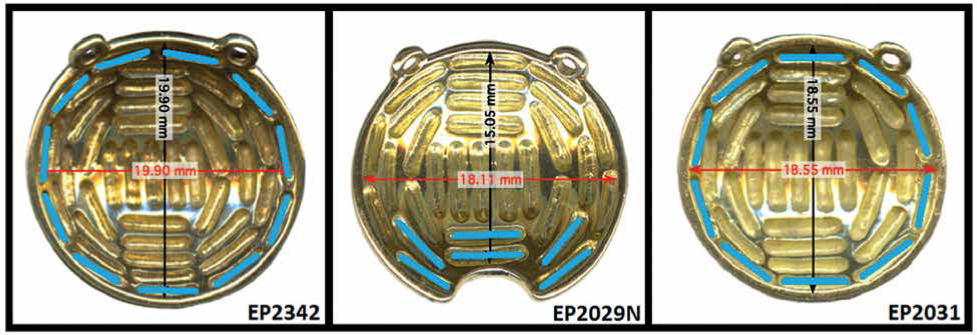
Plaque Simulator software was used to retrospectively plan 15 clinical cases, five each of the three following clinical scenarios: (1) Shallow (< 5.5 mm) tumors with large base dimensions (range, 16-19 mm) planned with EP2342, which is the largest plaque available from eye physics (23 mm diameter); (2) Tumors very near the optic nerve planned with EP2029N notched plaque (20 mm diameter); and (3) Very shallow (< 3.0 mm) tumors with moderate base dimensions (range, 13.5-15.5 mm), where an EP2342 plaque was used even though the ocular oncologist had requested an EP2031. These plaque models are shown in Figure 3. Clinical plans chosen for re-planning were prescribed to at least 2 mm deeper depth than the tumor apex in order to ensure target (base + 2 mm margin) coverage of at least 95% of the prescription. Tumors with an apex less than 5.5 mm were investigated in this study, because deeper tumors (> 5.5 mm) tended to not have to be planned using a deeper planning apex to achieve margin coverage. In these cases, prescribing to the actual depth of the tumor usually resulted in an acceptable margin coverage.
Dual-source strength seed loading
When deciding to use dual-source strength loading, two questions had to be answered: How much hotter should the higher source strength seeds be, and which seed locations should contain the higher source strength seeds. We used historical planar implant rules and clinical experience to inform these decisions in parallel, and an analysis of this determination can be found in the Discussion section.
For scenario (1), EP2342 plaques were planned with the outer ring of sources at twice the source strength of inner sources. For scenario (2), EP2029N plaques were planned with the six seeds closest to the notch at twice the source strength of other sources. For scenario (3), EP2031 plaques were planned with the outer ring of sources at twice the source strength of inner sources. Figure 3 shows photos of these plaques and illustrates these higher source strength seed locations (in blue color). Seed loading was kept symmetric for ease of loading, plaque QA, and plaque placement during plaque application. During re-planning, the prescription apices for the dual-source strength plans were chosen, to the nearest 0.1 mm, to achieve similar target coverage as the clinical plan.
Dosimetric analysis
Dosimetric endpoints were determined from the critical structure output from the PS TPS, which shows the dose to a point in various critical structures. Since the critical structures of interest (sclera, disc center, and fovea) were simulated as either 1D (fovea and disc center) or 2D (inner sclera) structures on the inner surface of the eye, point doses were used rather than volumetric doses. Point dose changes for each critical structure over the subset of patients representing a particular clinical scenario were averaged, and standard deviation was calculated.
Plaque loading and quality assurance
Because these EP plaques were loaded by the vendor and sent to the clinic as pre-sterilized plaque, there was no opportunity for a clinical physicist to independently verify the locations of the seeds of different source strength during seed loading process. It was necessary to work with the vendor to implement a process that ensured the clinical physicist certainty in the correct loading of the seeds. A test dual-source strength plan was made, and corresponding order was placed. The vendor constructed the plaque, and it was subsequently delivered to assess the workflow.
Results
In all the cases of large (range, 16-19 mm base dimension) shallow (< 5.5 mm tumor apex) tumors (see Table 1 for scenario 1), the dual-source strength plan was able to decrease the prescription depth by 0.8 mm to 1.3 mm. This overall decrease in planning apex resulted in doses to all critical structures being consistently lower in the dual-source strength plans by the following amounts: inner sclera –25% ±2%, optic disc –7% ±3%, and fovea –6% ±3% (average ± standard deviation). A representative set of plan comparisons can be seen in Figure 4.
Fig. 4
Scenario 1: EP2342 plaque isodose lines at the mid-plane with single-source strength plan (A) and dual-source strength plan (B)
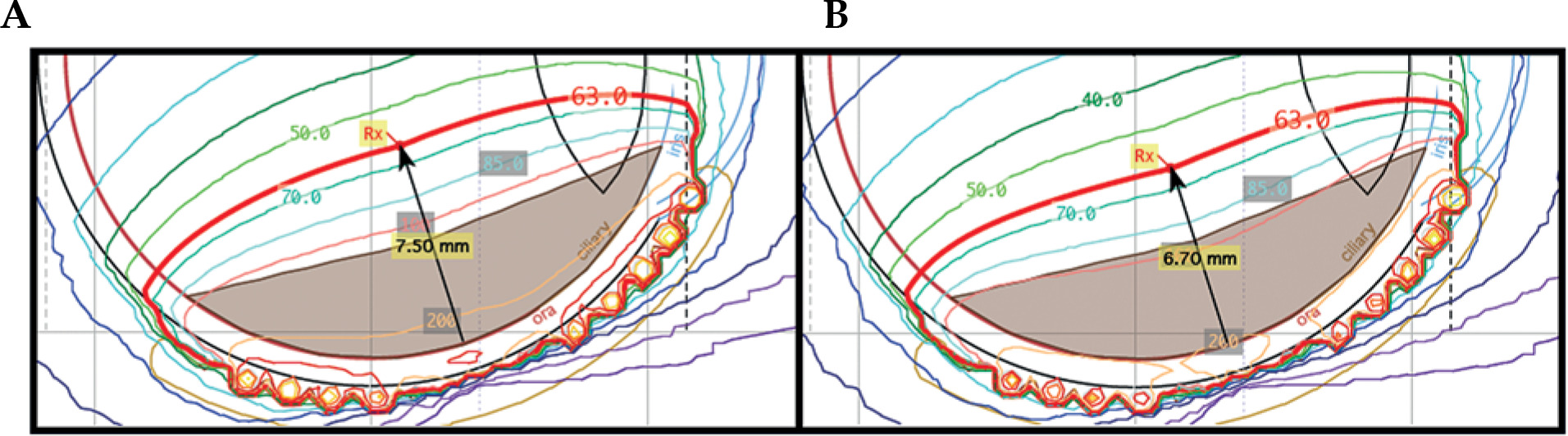
Table 1
EP2342 cases (scenario 1) re-planned using dual-source strengths in cases of large shallow tumors
In four out of the five tumors close to the optic nerve (see Table 2 for scenario 2), the dual-source strength plan was able to decrease the prescription depth by 0.4 mm to 0.7 mm. This variation was due to specific location of the tumor with respect to the optic nerve. In some cases, the tumor encroachment on the optic nerve is so substantial that dual-source strength loading does not result in a decreased planning apex. In all five of these cases, the dose to inner sclera was consistently lower in the plans with dual-source strength by 22% ±5%, and the dose to the optic disc and fovea were consistently higher by 17% ±7% and 20% ±12%, respectively. A representative set of plan comparisons can be seen in Figure 5. Therefore, the dual-source strength plans in case of a notched plaque can increase radiation dose to the optic nerve.
Fig. 5
Scenario 2: EP2029N plaque isodose lines on the inner surface of the eye with single-source strength plan (A) and dualsource strength plan (B)
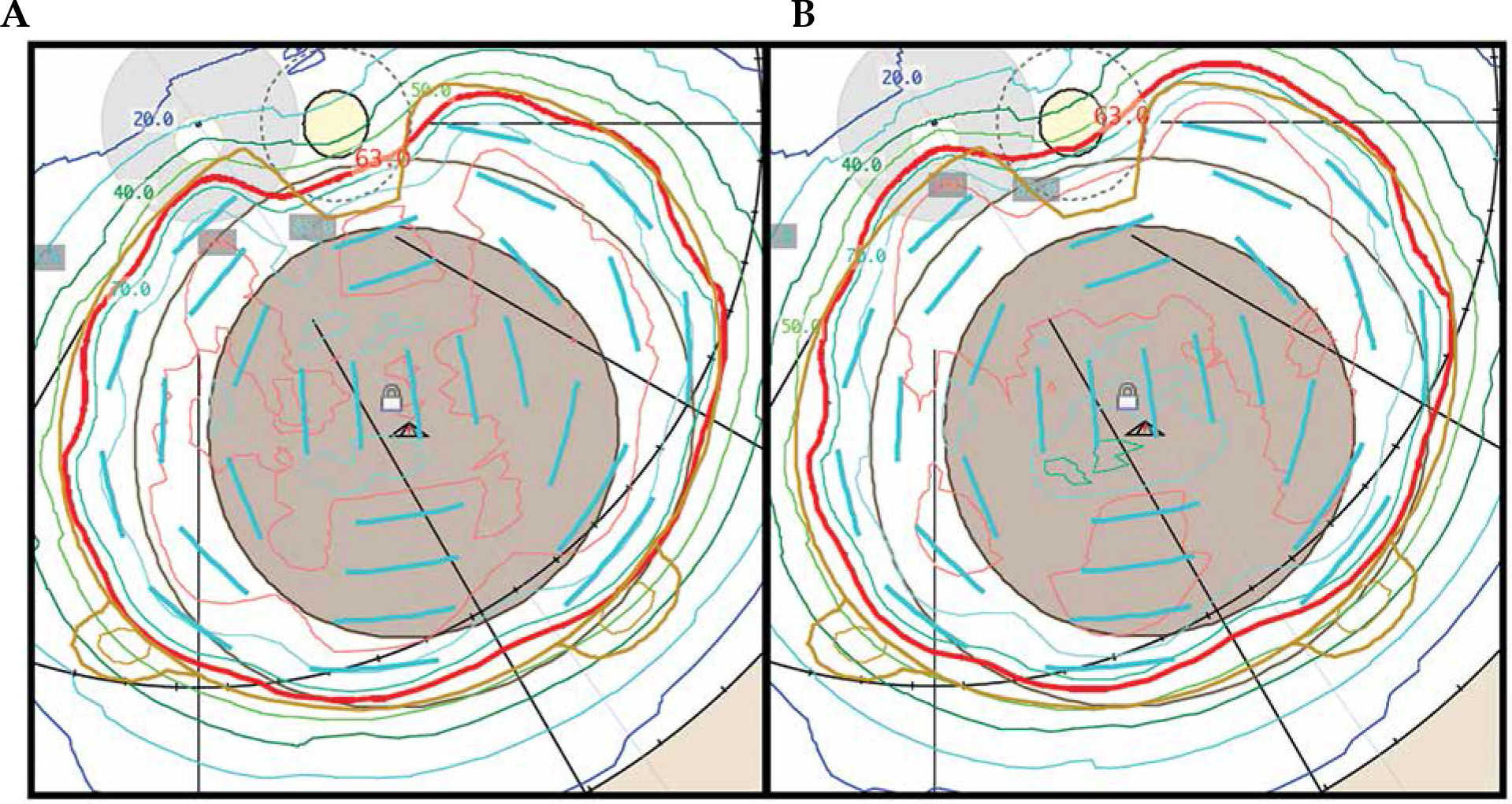
Table 2
EP2029N cases (scenario 2) re-planned using dual-source strengths in cases of tumors close to the optic nerve
In all the cases of very shallow (< 3.0 mm tumor apex) tumors with moderate base dimensions (range, 13.5-15.5 mm) (see Table 3 for scenario 3), the dual-source strength plan using the smaller EP2031 plaque was able to achieve the same margin coverage as when using the larger EP2342 plaque. The planning apex depth increased by 0.2 mm to 0.8 mm when using the smaller plaque. These re-plans resulted in dose to sclera decreasing by –45% ±3%, while dose to the optic disc and fovea was modestly increased or decreased in the dual-source strength plans depending on the location of tumor related to these structures: optic disc 1% ±14% and fovea 5% ±5%. A representative set of plan comparisons is presented in Figure 6.
Fig. 6
Scenario 3: isodose lines both at mid-plane and on the inner surface of the eye for EP2342 single-source strength plan (A) and EP2031 dual-source strength plan (B)
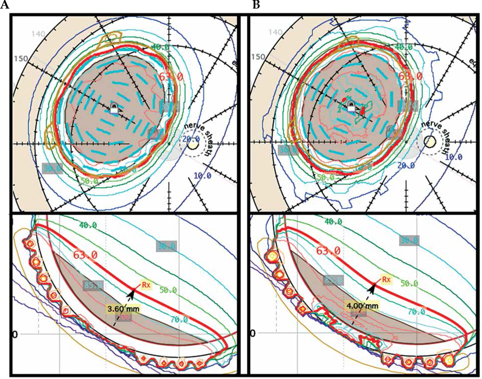
Table 3
EP2342 single-source strength plans (scenario 3) re-planned using dual-source strength EP2031 plans in the case of very shallow tumors with moderate base dimensions
For plaque ordering, two separate orders were submitted by the clinical physicist, one for each source strength. Included in the order were two non-sterile loose seeds from each of the two batches used to load the plaque. The dual-source strength treatment plan was submitted with each order. During the seed loading process, the vendor took photos after loading one source strength and before proceeding with the second source strength, and then took a second photo after fully loading the plaque. These photos are included in Figure 7, and indicate the respective order number associated with the order placed for that source strength seed. After being received by the clinical physicist, the two loose seeds from each batch were assayed to confirm the source strength of each batch. This was similar to the technique utilized in our prior experience with COMS plaques, when dual-source strength loading was necessary due to lack of seed inventory. In those cases, a second independent physicist would review the seed loading of the first source strength before the loading of the second source strength commenced. In this new technique of intentionally using two source strengths, a photo of the loading and the order number associated with that source strength would take the place of the second independent physics’ check. These additional QA steps were necessary to ensure that the plaque was loaded by the vendor to the specifications provided by the physicist.
Fig. 7
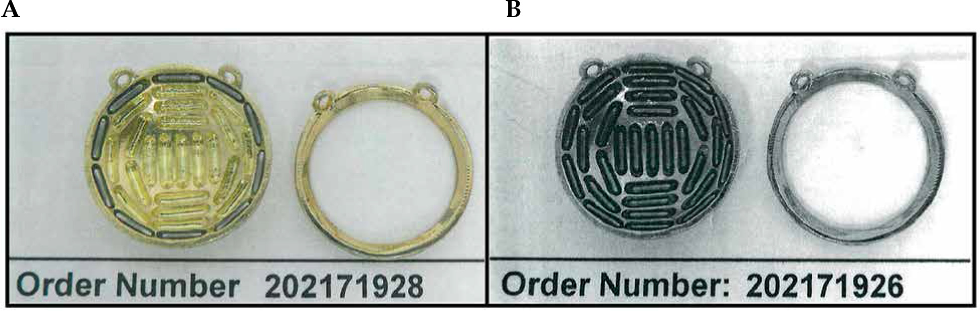
Photographs are taken by the vendor twice during the seed loading process, once after loading the higher source strength seeds (A), and once after loading the remaining source locations with the lower source strength seeds (B). The order numbers in the photos are those associated with the order made for the seeds being loaded at that point in the loading process
Discussion
Determination of source strength ratios
The use of dual-source strength plaque loading to improve dose coverage of the target and minimize dose to OARs has been investigated in COMS plaques [19], but the differences in design between COMS and EP plaques required further investigation. Moreover, as shown here, the specific clinical scenario with relation to the size, shape, and location of the tumor influence dual-source strength plaques change in the dose to OARs. Maintaining the confidence of clinicians with our process was just as significant as dosimetric improvement. For that reason, a moderate approach was taken that utilized the outer ring of circular plaques, and the six seeds closest to the notch of notched plaques, being replaced with seeds that were twice the source strength of the inner seeds.
Historical Paterson-Parker (P-P) implant guidelines for planar implants less than 25 cm2 in size, recommend 67% of the source strength to be in the periphery of the implant and 33% in the center. They also recommend the use of crossing needles on the periphery of the implant [28]. That would suggest that for the EP2342 (42 total seeds, 11 in the outer ring), the outer ring of sources should be 6.3 times stronger than the inner sources, and for the EP2031 (31 total seeds, 10 in the outer ring), the outer ring of sources should be 4.4 times stronger. However, plaques differ from traditional P-P implants in that the plaque is curved along the surface of the eye, the sources are closer than 1 cm, and that they are significantly smaller than standard planar implants. Whereas P-P recommendations have break points at 25 cm2 and 100 cm2, even the largest EP plaque has a nominal area of only 4.2 cm2, much smaller than even the smallest subset of P-P implants. For these reasons, we expected the difference between high source strength and low source strength seeds to be less than a standard P-P implant might suggest. The use of crossing needles of the same source strength as the inner needles suggested that a peripheral source strength twice that of the inner source strength might be appropriate. The clinical differences when planning using high source strength sources that were 1.5, 2.0, and 3.0 times the source strength of the low source strength sources, were investigated by retro-actively planning a single clinical case of scenario 1 using seeds with those ratios of source strengths. The prescription apices for the different ratios of source strengths were chosen, to the nearest 0.1 mm, to achieve similar target coverage as the clinical plan. For the notched plaque, as the primary goal was to increase dose adjacent to the notch, using high source strength seeds in both the closest three and the closest six seeds to the notch was investigated, while maintaining the same ratio of source strengths chosen after the study of circular plaques. The source strength ratio used for the notched plaque plans was intentionally kept the same as in the circular plaques for clinical simplicity.
The differences in planning a case of scenario 1 with high to low source strength seed ratios of 1.5, 2.0, and 3.0 are presented in Figure 8 and Table 4. Although a ratio of 3.0 did provide the most substantial change by decreasing the planning apex by 1.5 mm and decreasing scleral dose by over 35%, shifting to a method that utilized seeds of such disparate source strength differences caused some concern within the clinical group, because all clinical experience was based on trying to achieve a uniform seed source strength across the plaque. It was determined that a ratio of 2.0 provided acceptable clinical change without altering the planning paradigm so substantially as to call into question knowledge based on our prior clinical experiences. For ease of clinical planning and to avoid introducing planning error, it was also decided that the ratio of 2.0 between seed source strengths would remain consistent in different sized circular plaques, and would also be used for notched plaques. For this reason, source strength ratios were not re-optimized for notched plaque scenarios. Figure 9 and Table 5 show the difference between planning a case of scenario 2 while using high source strength seeds in the three seeds, or in the six seeds, closest to the notch. It was decided that due the increased margin coverage near the optic nerve obtained by using high source strength seeds in the six locations closest to the notch, which would be the technique used to re-plan the clinical cases. It should be decided on a case-by-case basis if this increased margin coverage near the optic nerve warrant an increase in the dose to the optic nerve and fovea.
Fig. 8
A case of scenario 1 planned with a single-source strength and with seed source strength ratios of 1.5, 2.0, and 3.0
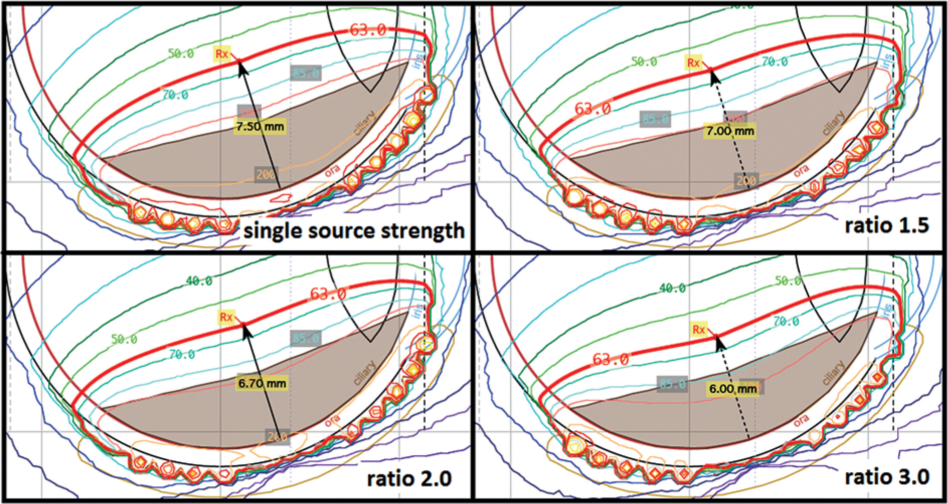
Fig. 9
A case of scenario 3 planned with a single-source strength and with a seed source strength ratio of 2.0 with three seeds closest to the notch and six seeds closest to the notch replaced with higher source strength seeds
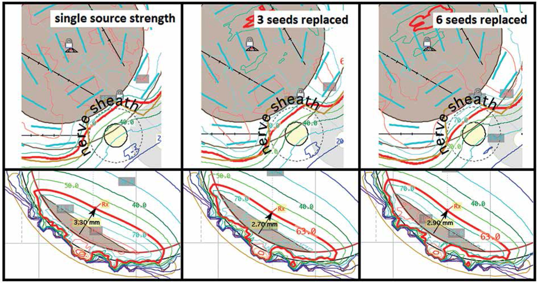
Table 4
Change in dose to OARs for a case of scenario 1 planned with a single-source strength and with seed source strength ratios of 1.5, 2.0, and 3.0
Table 5
Change in dose to OARs for a case of scenario 3 planned with a single-source strength and with a seed source strength ratio of 2.0 with three seeds closest to the notch and six seeds closest to the notch replaced with higher source strength seeds
Clinical application of dual-source strengths
For large (range, 16-19 mm base dimension) shallow (< 5.5 mm tumor apex) tumors (scenario 1), dose to critical structures was constantly improved due to shallower prescription depth that could be achieved by loading the outer ring of source locations with higher source strength seeds. The largest dose reduction occurs to the inner sclera and the adjacent retina, because they are closest to the plaque, but changes in other critical structures are patient-specific depending on the location of the tumor in the eye, and it may be beneficial to discuss dual-source strength loading when the EP2342 plaque is used. As this is the largest plaque offered by eye physics, this planning approach may allow it to be used for larger tumors, while maintaining reasonable dose to critical structures.
For tumors near the optic nerve (scenario 2), dose to the critical structures by the use of dual-source strength seed loading varied. Although scleral dose was decreased, dose to the optic disc and fovea were increased because the seeds located closer to the optic nerve had higher source strength, and resulted in an increased coverage of the margin under the optic nerve sheath. As this difference is due to the location of the tumor relative to the optic nerve and fovea, it may be beneficial to investigate dual-source strength plans on a case-by-case basis if scleral dose is a concern for a particular patient, or if it is necessary to try to increase radiation dose to cover tumor against the optic nerve, but it is not clear that using dual-source strengths will always improve brachytherapy plans in these cases.
For very shallow tumors (< 3.5 mm tumor apex) with moderate base dimensions (range, 13.5-15.5 mm) (scenario 3), dose to sclera decreased with a smaller plaque using dual-source strength, even though the planning apex height increased. This is due to the use of different plaques with different scleral offsets. Moreover, this was the only scenario where re-plans were performed with different plaque models; therefore, this was the only scenario with this consideration. Because the dose to the optic nerve and fovea are farther away from the surface of the plaque, the scleral offset had no effect on these comparisons, and these dose differences varied depending on the relative tumor location to these OARs in each specific clinical case. However, the goal of dual-source strength loading in this clinical scenario is not to decrease the dose, rather it is to allow the ocular oncologist to use the preferred plaque based on the individual patient’s anatomy, surgical considerations, and tumor location. For this reason, it may be beneficial to communicate with the ocular oncologist and radiation oncologist regarding any patients who may benefit from the use of a smaller plaque using dual-source strength loading.
Prior clinical use of dual-source strengths
Patients treated with COMS plaques at our institution in a dose de-escalation study [16, 17] included patients who were treated with plaques containing dual-source strengths, but rather that using dual-source strengths to increase conformality in those cases, the dual-source strengths were used due to limited supply of seeds from the previous vendor. Therefore, in these cases, the source strengths were chosen to be as close to each other as possible in order to maintain a plaque loading pattern approximating single-source strength loading. A two-physicist loading procedure was established for those prior cases where the plaques were loaded in-house, and a similar QA technique incorporating photos from the vendor was applied to ensure the correct plaque loading for these pre-loaded plaques.
Limitations and future work
Because the transfer of actual tumor location to the location of tumor in TPS is an estimate based on fundus diagrams, the absolute values of the dose to the critical structures provided here is only an estimate. However, if used with an imaged-based planning paradigm, the dose to critical structures and any reduction due to dual-source strength planning can be determined more precisely. The optimization of source strength ratios on a per-scenario or per-patient basis may be addressed in the future, once this technique becomes established in the clinic and good patient outcomes are proven. Dual-source strength plaque loading may be beneficial for obtaining margin coverage when using other types of eye plaques as well if margin coverage can be determined using an appropriate treatment planning system that accounts for inhomogeneities.
Conclusions
For large (range, 16-19 mm base dimension) shallow (< 5.5 mm tumor apex) tumors, dose statistics were universally improved in the patients studied, and dual-source strength loading should be considered for these tumors planned with the largest circular plaque available from eye physics. For tumors near the optic nerve, the results showed that although the scleral dose was decreased, dose to the optic disc and the fovea were increased based on the tumor location relative to those OARs. Therefore, dual-source strength plans should be carefully considered on a case-by-case basis if scleral dose is a concern because dose to the optic nerve and fovea would likely to increase. For very shallow (< 3.0 mm tumor apex) tumors with moderate base dimensions (range, 13.5-15.5 mm) that were planned with a larger plaque than was requested by the ocular oncologist, the requested plaque size with dual loading may be used as a good alternative. Due to the varying changes in critical structure, the choice of the plaque used for planning should be discussed with the ocular oncologist and radiation oncologist. In general, the use of dual-source strengths should be considered on a case-by-case basis, and patient outcomes should be closely followed. The use of this technique also requires additional careful QA of the plaque loading, and may warrant integrating volumetric imaging rather than the fundus diagrams currently used for treatment planning.


