
Purpose
Cervical cancer treatment consists of surgery, chemotherapy, and radiotherapy. Radiotherapy typically involves external beam radiation therapy (EBRT) to treat the tumor and pelvic lymph nodes, followed by brachytherapy to deliver high radiation dose directly to the tumor. In brachytherapy, applicator is inserted into the uterine cavity to enable precise radiation delivery by a remote afterloader, which positions high-activity sources within the applicator channels. Although advanced radiotherapy techniques, such as intensity-modulated radiation therapy (IMRT) and stereotactic body radiation therapy (SBRT) provide improved target coverage and reduced side effects to surrounding organs, the use of brachytherapy has declined due to its invasive nature. However, studies have shown that combining brachytherapy with EBRT leads to lower recurrence rates and higher survival rates when compared with EBRT alone [1-4]. Therefore, brachytherapy remains an essential component of cervical cancer treatment.
One of the key advantages of brachytherapy is its steep dose gradient, allowing the delivery of high radiation dose to the tumor while minimizing exposure to surrounding normal tissues [5]. The Groupe Européen de Curiethérapie-European Society for Therapeutic Radiology and Oncology (GEC-ESTRO) recommends using 3D image-guided brachytherapy (IGBT) with computed tomography (CT) or magnetic resonance imaging (MRI) instead of traditional 2D brachytherapy, as it enables better delineation of tumors and adjacent organs [6, 7].
Our center has installed an in-room CT dedicated to brachytherapy in 2019. After insertion of brachytherapy applicators, patients are transferred to a CT room, where CT image acquisition and brachytherapy dose delivery can be performed in a loading room without the need to move the patient. However, our center has a high patient workload; therefore, it is required to replace patients from CT table during the planning process, and then transfer them back for brachytherapy dose delivery, despite the CT machine located within the brachytherapy loading room, supporting the overall duration of treatment [8]. Such a movement can lead to applicator displacement, which is a critical concern due to brachytherapy steep dose gradient. Even minor shifts in the radiation source position can result in significant changes in dose distribution, potentially affecting both tumor coverage and dose delivered to organs at risk (OARs) [9].
The American Brachytherapy Society recommends that the applicators be fixed to the treatment bed to prevent displacement; however, uterine perforation remains a potential risk [1]. To reduce applicator movement during patient transfer, methods, such as external fixation and patient transport systems with leg support, are employed to maintain the patient position. In 2023, the Division of Radiation Oncology, Faculty of Medicine, Chiang Mai University, adopted a new patient transfer system for brachytherapy (Klarity Medical and Equipment Company Limited, Guangzhou, China), replacing the traditional method that increased workload and the risk of accidents during transfers. The primary objective of the new transfer system is to improve workflow efficiency and minimize applicator displacement during patient movement.
In this study, we aimed to evaluate applicator displacement during patient transfer, comparing the use of traditional fixation with and without the patient transfer system, and to assess the dosimetric impact on OARs.
Material and methods
In this retrospective study, we analyzed 32 patient datasets, with ages ranging from 35 to 88 years. These patients were diagnosed with cervical cancer (stages IIA-IVA), and received treatment at the Division of Radiation Oncology, Faculty of Medicine, Chiang Mai University, between February 2020 and November 2024. All patients initially received EBRT with 50 Gy in 25 fractions or 46 Gy in 23 fractions, followed by CT-based high-dose-rate (HDR) brachytherapy using Nucletron, Flexisource Ir-192 source. Brachytherapy was delivered with either 4 fractions of 7 Gy (total, 28 Gy), or 3 fractions of 8.5 Gy (total, 25.5 Gy). Cumulative dose of external beam radiotherapy and brachytherapy to high-risk clinical target volume (HR-CTV) was prescribed to reach a minimum of 80 Gy in EQD2. This study was granted an ethics exemption by the Research Ethics Committee of the Faculty of Medicine, Chiang Mai University (study code: RAD-2567-0599; research ID: 0599).
Patient transport method
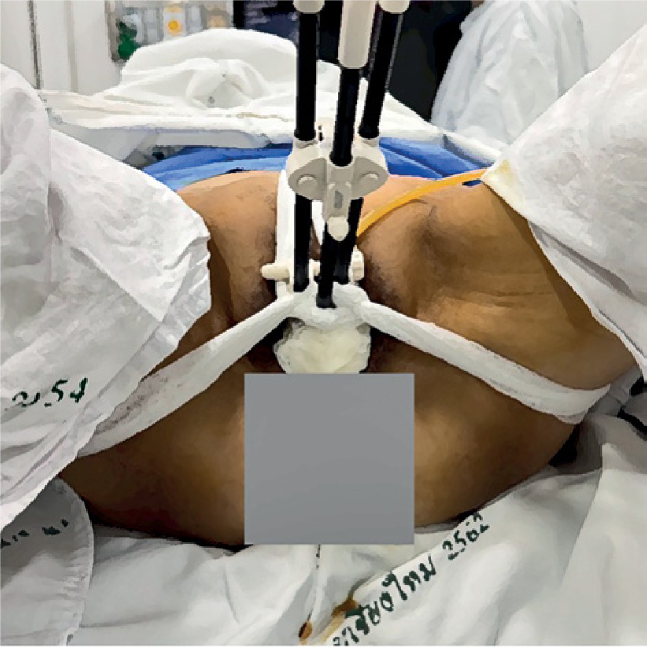
At our center, traditional fixation is used to prevent applicator displacement, which may occur between imaging and dose delivery, leading to dose variations in target volume and normal organs. The traditional fixation protocol includes vaginal gauze packing, three-point gauze external fixation (Figure 1), bladder volume maintenance protocol, and rectal preparation. Patients are advised by a radiation oncologist to follow a soft or liquid diet for three days before treatment to optimize rectal conditions.
Fig. 1
Traditional fixation method (TRD). Three-point gauze external fixation, with a central point at the perineal area, and two lateral points at the hip/thigh area
Previously, our center utilized traditional fixation in combination with a traditional transport method (TRD), where patients were transferred using a stretcher into a CT room. Horizontal transfer between beds was performed manually by a team of healthcare workers with a slide board.
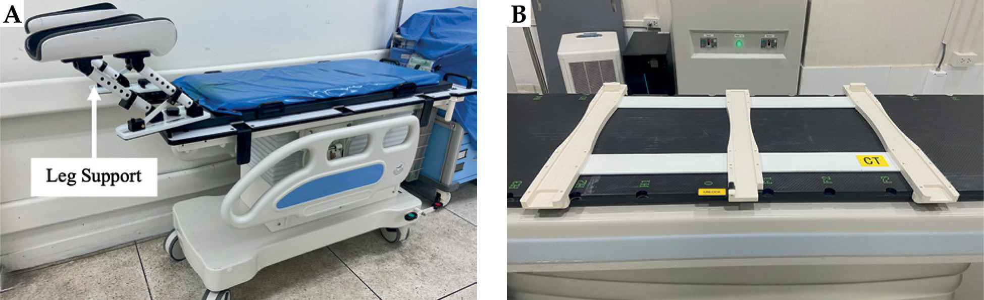
Currently, we adopted a new transport method that integrates traditional fixation with a patient transfer system (TRD + TS). This patient transfer system consists of two main components: transfer aid and leg support. These devices are designed to securely lock in place, ensuring patient safety during transfer (Figure 2).
Fig. 2
Patient transfer system consists of two main components: A) Leg support is tilting angle adjustable, allowing the patient to maintain the same position, and B) transfer aid is placed on the CT couch, functioning as a sliding rail to facilitate patient transfer
This study aimed to compare two patient transfer systems using two patient groups, i.e., the TRD system (23 fractions, 18 patients), and the TRD + TS system (23 fractions, 14 patients).
Treatment procedure
CT images, including those of target and OAR structures, were obtained from 46 treatment plans involving 32 patients diagnosed with cervical cancer. These patients underwent HDR brachytherapy using either a Fletcher-Williamson or Geneva tandem and ovoid applicator (Elekta, Inc., Stockholm, Sweden). Applicators were inserted by a radiation oncologist, and gauze packing was applied to minimize applicator movement. Additionally, a three-point gauze external fixation technique was utilized to stabilize the applicators. A Foley balloon catheter was placed in the bladder to ensure proper volume control during treatment.
Before imaging, the bladder was emptied and subsequently filled with 100 ml of contrast solution diluted in normal saline solution (NSS) to enhance visualization. Patients were then transferred for CT imaging using Alexion™ (Canon Medical Systems, USA) scanner installed in brachytherapy loading room, with a 2-3 mm slice thickness. After image acquisition, patients were moved to waiting area, and NSS from the bladder was released.
The acquired CT pre-plan images were exported to Oncentra brachytherapy treatment planning system (version 4.6.3, Nucletron, Veenendaal, Netherlands) for treatment planning, using TG-43 algorithm. Target and OAR delineation were performed following GEC-ESTRO recommendations [6, 7]. A radiation oncologist used TRUS or TAUS to guide HR-CTV contouring. For intermediate-risk clinical target volume (IR-CTV), the radiation oncologist draws it to represent pre-EBRT volume. OARs, including the bladder, rectum, sigmoid, and bowel, were localized accordingly. After brachytherapy plan approval, patients were transferred back to the brachytherapy loading room. The bladder was refilled with 100 cm3 of saline before dose delivery. A second CT scan (CT pre-load) was performed to verify applicator positioning, ensuring consistent bladder filling as in routine workflow before treatment delivery. Applicator shift between planning and dose delivery was assessed by comparing CT pre-plan and CT pre-load images.
Applicator displacement measurement
Applicator displacement was quantified using rigid image registration in MIM Maestro® (MIM Software Inc., Ohio, USA) by aligning two CT datasets, i.e., CT pre-plan and CT pre-load, based on pelvic bony structures. The measurement methodology was adapted from Shi et al. [10], where displacement was determined by calculating the distance between the applicator base in the two images. CT pre-plan served as the primary image, while CT pre-load was the fused image, with measurements obtained using dedicated image analysis tools.
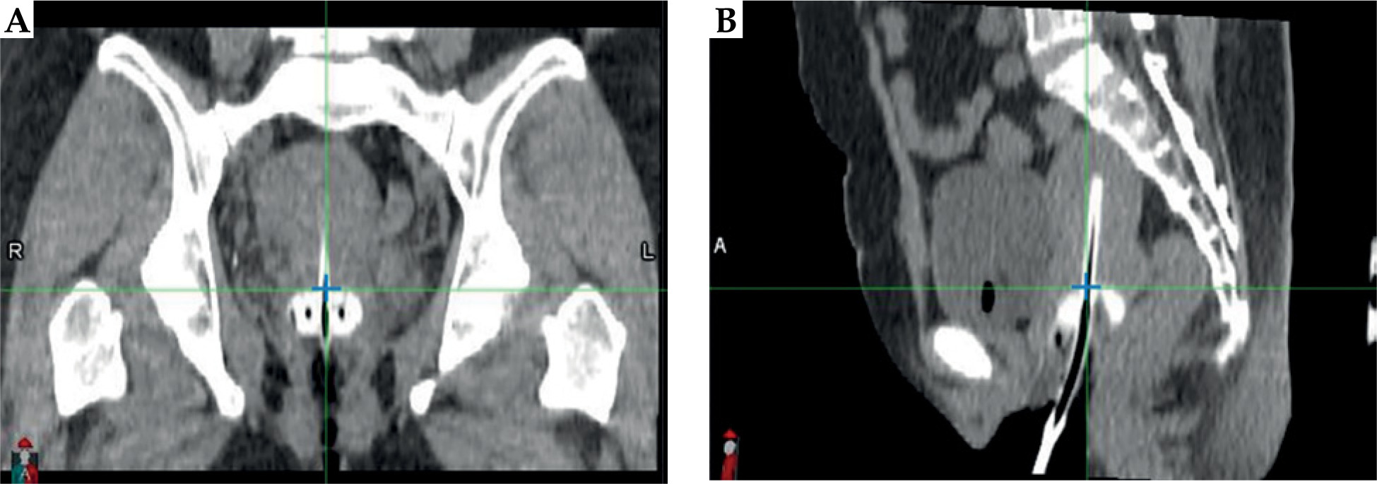
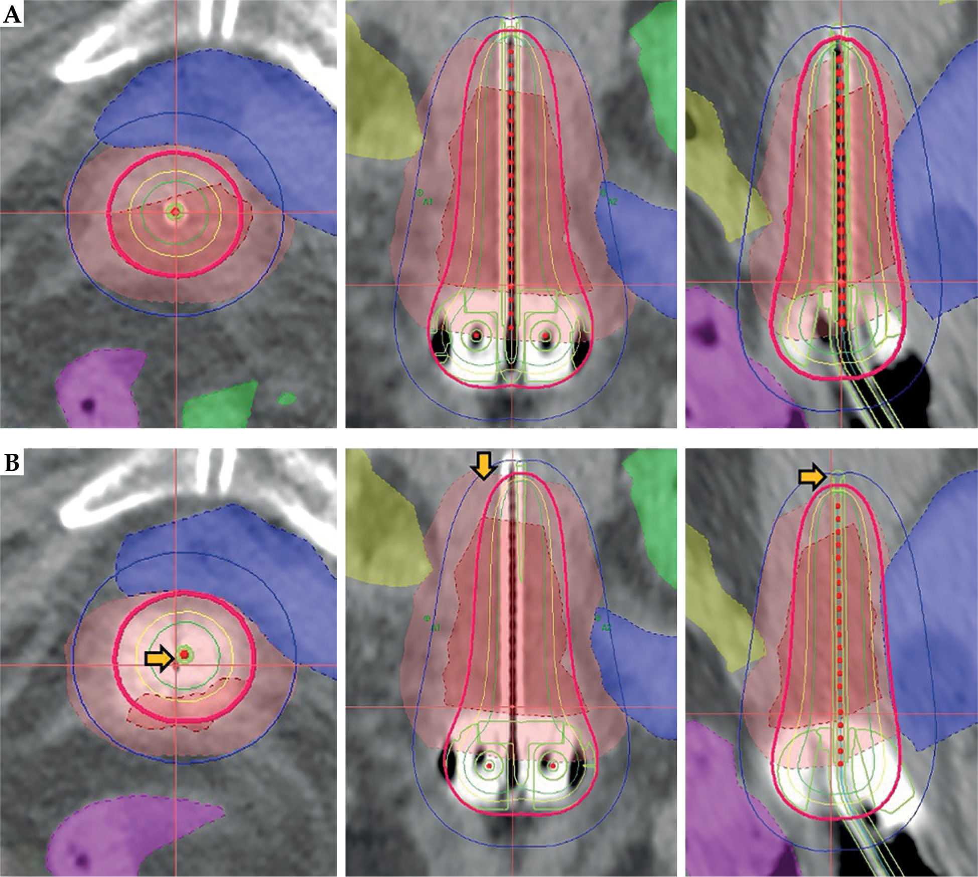
Applicator base (reference point) was identified in transverse plane by aligning it with the ovoid surface, as illustrated in the sagittal view in Figure 3B. In sagittal plane, the reference point was defined based on the midline of tandem, as observed in the coronal view in Figure 3A.
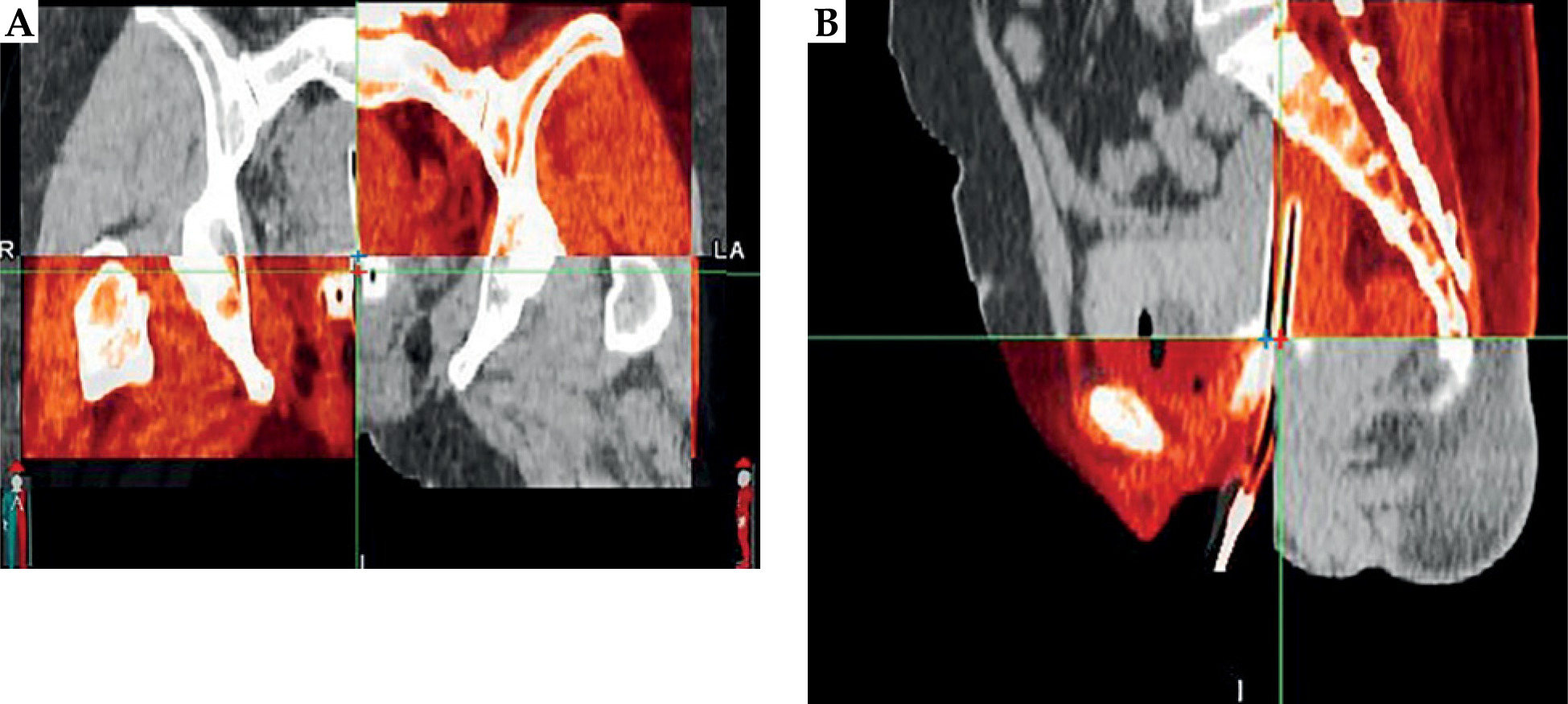
Applicator displacement was assessed along three axes: X-axis (rightward as negative, and leftward as positive), Y-axis (inferior as negative, and superior as positive), and Z-axis (anterior as negative, and posterior as positive). Figure 4 demonstrates a case, in which the applicator shifted in the inferior and posterior directions between CT pre-plan and CT pre-load images.
Simulated applicator displacement
To assess the dosimetric impact on OARs, simulated displacement treatment plans were created using Oncentra treatment planning system (version 4.6.3, Nucletron, Veenendaal, Netherlands). Applicator position from original treatment plan (CT pre-plan) was virtually shifted based on individual magnitude and direction of displacement observed for each patient (Figure 5).
Analysis of dosimetric impact on OARs
Radiation dose to OARs was compared by calculating the percentage difference between virtually simulated displacement plan (simulated shift plan) and original treatment plan (original plan), using the following formula: percent dose difference = (simulated shift plan – original plan)/original plan (%).
Doses to OARs (the bladder, rectum, sigmoid, and bowel) were evaluated at D2cc.
Statistical analysis
Data were assessed for normality using Shapiro-Wilks test. For comparisons between the two transport systems, unpaired Student’s t test was applied for normally distributed data, while Mann-Whitney U test was employed for non-normally distributed data. Results were presented as means with 95% confidence intervals (CIs) or p-values, as appropriate. All statistical analyses were conducted using IBM SPSS version 27.0.1 (IBM Corp., Armonk, New York, USA).
Results
Applicator displacement
The displacement measurements for both groups (TRD and TRD + TS) are summarized in Table 1 and illustrated in Figure 6. The applicator displacement for both groups generally shifted towards the left (+X) and inferior (–Y) directions, with mean displacements of 0.58 mm and –0.71 mm for the TRD group, and 0.15 mm and –0.33 mm for the TRD + TS group, respectively. In the anterior-posterior direction, the applicator in the TRD group tended to move posteriorly (+Z), with a mean displacement of 0.49 mm, while the TRD + TS group exhibited a tendency to move anteriorly (–Z), with a mean displacement of –0.23 mm. No significant differences were observed between the TRD and TRD + TS groups in any direction. Additionally, no significant shifts in applicator displacement were noted between the imaging (CT pre-plan) and dose delivery (CT pre-load) for neither group.
Table 1
Comparison of applicator displacement between two patient transfer systems: TRD and TRD + TS
Fig. 6
Box plot illustrating the comparison of applicator displacement for traditional (TRD) and traditional plus patient transfer system (TRD + TS) along X, Y, and Z axes. A negative value indicates displacement in the right, inferior, and anterior directions, while a positive value indicates displacement in the left, superior, and posterior directions
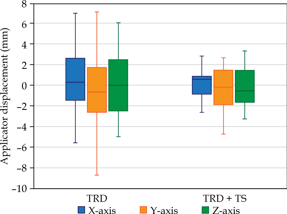
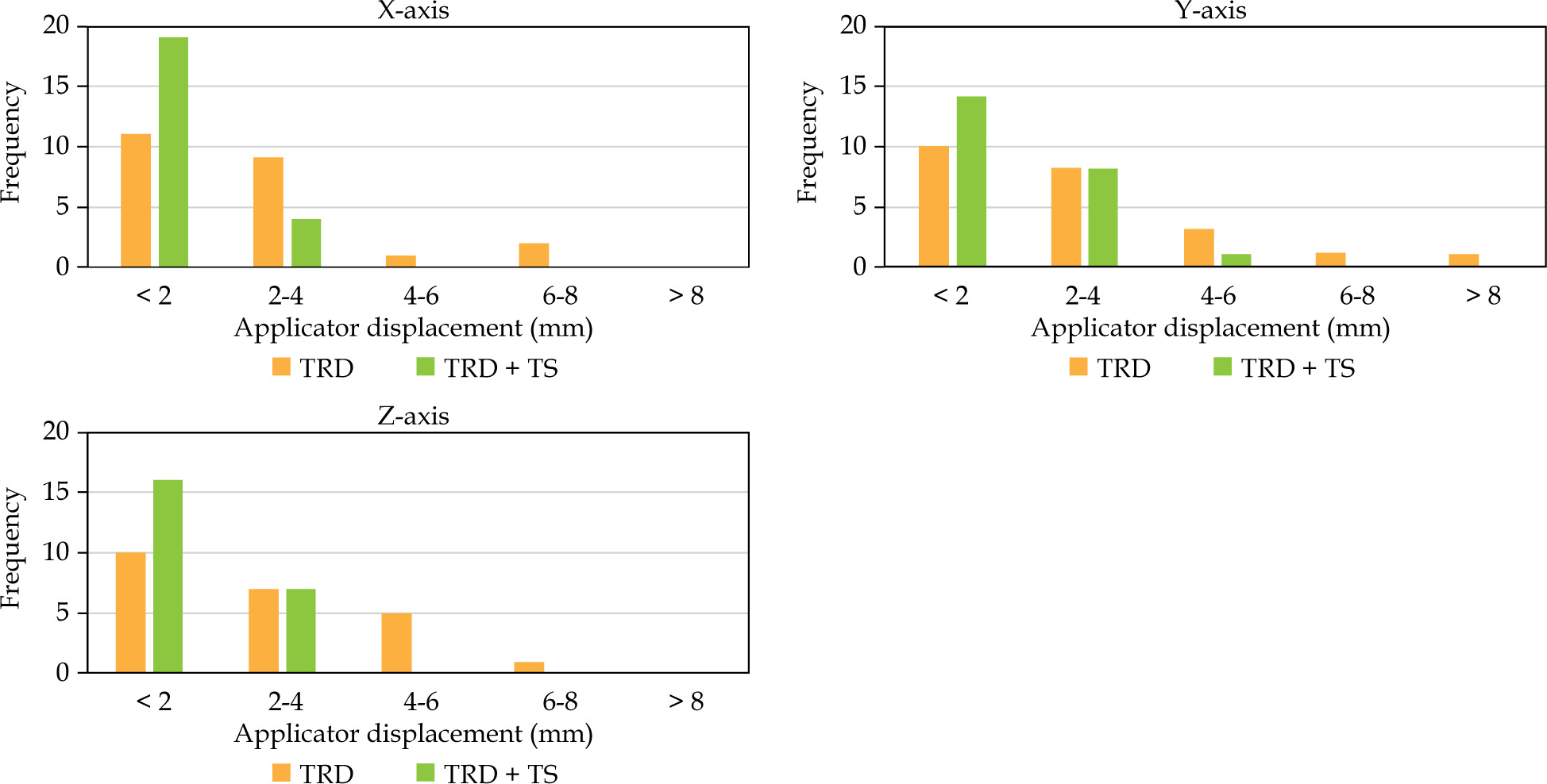
Root mean square (RMS) values were calculated to assess the magnitude of displacement, ensuring that negative values did not compensate for positive values. The TRD + TS group showed a reduction in applicator displacement across all directions. Specifically, on the X-axis, displacement decreased from 2.94 mm (TRD) to 1.43 mm (TRD + TS); on the Y-axis, from 3.45 mm (TRD) to 2.00 mm (TRD + TS); and on the Z-axis, from 3.17 mm (TRD) to 1.83 mm (TRD + TS). The frequency distribution of magnitude displacement ranges (0-2 mm, 2-4 mm, 4-6 mm, 6-8 mm, and > 8 mm) is shown in Figure 7. Notably, displacements exceeding the 4-6 mm range were less frequent in the TRD + TS group than in the TRD group.
Dosimetric impact of applicator displacement
In Table 2, the changes in dose to D2cc for the bladder, rectum, sigmoid, and bowel, are presented. The average dose increases were 0.54%, 8.39%, 3.78%, and 0.58% for TRD, and 3.19%, 1.66%, 2.83%, and 1.19% for TRD + TS, respectively, when the applicator was virtually shifted along the X, Y, and Z axes for the simulated plans. No significant differences were found between the two groups in these dose changes.
Table 2
Mean and standard deviation of D2cc to the organ at risk (OAR) for individual simulated applicator displacements in TRD and TRD + TS
Discussion
Brachytherapy for cervical cancer is a highly effective modality for increasing the radiation dose to the tumor while minimizing the exposure to surrounding organs at risk. This is mainly attributed to the sharp dose gradient surrounding the radiation source. Ensuring that the dose planning geometry closely aligns with the treatment geometry is crucial, as any discrepancies between the two could adversely affect treatment outcomes and tumor control.
In this study, traditional fixation techniques were employed to minimize the risk of applicator displacement; however, some movement was still observed. In the lateral direction, the applicators tended to shift leftward on average. This displacement may be attributed to the patient transfer method to the CT couch, which is typically conducted from the left side at our center. In the anterior-posterior direction, displacement was relatively balanced in both directions, suggesting that internal organs movement was significantly impacted. Despite the consistent bladder protocol applied to both the groups, variations in displacement were observed, indicating that internal organ motion should be carefully considered during the process of brachytherapy treatment. To minimize anterior-posterior displacement, it is recommended to maintain a bladder-rectum protocol. Additionally, minimizing the time interval between imaging for treatment planning and treatment dose delivery could reduce the impact of internal organ movement. In the superior-inferior direction, the applicators tended to shift inferiorly, which is consistent with anatomical expectations. Since the applicators were inserted into the uterine cavity, there was a potential for them to move downward along the vaginal canal.
There is limited published data on applicator displacements (Table 3 [10-14]). In this study, a minimal displacement was observed in the lateral direction, consistent with findings from studies by Shi et al. [10], Peroff et al. [11], and Balsdon et al. [14], demonstrating an average displacement (RMS) of 2.94 mm for the TRD group and 1.43 mm for the TRD+TS group. This minimal movement may be attributed to the design of applicators, where the ovoid abutment against the vaginal wall, along with the tandem abutment in the endo-cervix, contributed to stability [15]. Additionally, the applicators were secured within the uterine cavity using gauze packing. In contrast, the maximum displacement was observed in the longitudinal direction, with an average inferior displacement of 3.45 mm for the TRD group and 2 mm for the TRD + TS group. This finding is consistent with previous studies, reporting the greatest applicator displacement occurring in the superior-inferior direction [10, 11]. Furthermore, some studies have specifically focused on longitudinal displacement [12, 13, 15], as this direction is the most probable anatomical path for the applicator to shift away from the cervix along the vaginal canal.
Table 3
A comparison of key findings from this study with other research on applicator displacements
| Study | Images modality | Applicator type | Lateral X-axis (mm) | Longitudinal Y-axis (mm) | Vertical Z-axis (mm) |
|---|---|---|---|---|---|
| Shi et al. [10], 2015 | 3D | T&O | 0.16 | 2.14 | 1.90 |
| Peroff et al. [11], 2016 | 2D | Ring | 1.74 | 5.57 | 5.27 |
| Karlsson et al. [12], 2017 | 2D/3D | Ring | – | 0.70 | – |
| Andrew et al. (Manual) [13], 2018 | 2D | T&O | – | 3.14 | – |
| Andrew et al. (Hover) [13], 2018 | 2D | T&O | – | 2.27 | – |
| Balsdon et al. [14], 2019 | 2D | Ring | 1.90 | 3.00 | 9.50 |
| Current study TRD | 3D | T&O | 2.94 | 3.45 | 3.17 |
| Current study TRD + TS | 3D | T&O | 1.43 | 2.00 | 1.83 |
This study aimed to compare applicator displacement and its subsequent impact on dose variation with OARs between two patient transfer systems: TRD and TRD + TS. Our analysis revealed no statistically significant difference in applicator displacement between the two systems. It is important to note that the TRD method used in this study already demonstrated very low displacement values, with mean displacements of X = 0.58 mm, Y = 0.71 mm, and Z = 0.49 mm. For comparison, Shi et al. [10] reported displacement values of X = 0.16 mm, Y = 2.14 mm, and Z = 1.9 mm, indicating that our TRD method yields significantly smaller displacements in the Y and Z directions. Furthermore, when combining TRD with TS, the displacement values were further reduced to X = 0.15 mm, Y = 0.33 mm, and Z = 0.23 mm. Even though these reductions represent an improvement, the differences between TRD alone and TRD + TS were not statistically significant due to the already minimal displacement achieved by TRD. Moreover, no significant difference in the radiation dose to OARs was observed. However, the rectum was the most affected organ in the TRD group, exhibiting an 8.39% increase in radiation dose due to applicator displacement in the posterior direction. In contrast, the bladder was the most affected organ in the TRD + TS group, showing a 3.19% increase in radiation dose due to applicator displacement in the anterior direction.
The impact of applicator displacement on radiation dose was assessed using virtual shifts within the treatment planning system (TPS). This approach has inherent limitations, as it assumes that the structure size and shape remain unchanged before and after applicator displacement. Displacements were derived from simulated shifts of the applicator. However, the calculated radiation dose represents a worst-case scenario, considering that tissues and organs may also move along with the applicator [14]. Previous studies have employed this method to investigate the dosimetric effects of applicator displacement [12, 14-17]. When utilizing virtual shifts, the dose to OARs is directionally dependent. For example, anterior displacement increases the bladder dose, whereas posterior displacement decreases the dose. If the patient cohort exhibits similar displacements in opposite directions, the average dose variation remains minimal. This explains why the TRD group exhibited less dose variation in the bladder compared with the TRD + TS group, where the displacement was predominantly anterior. These findings underscore the challenges associated with organ motion and volume changes, emphasizing the need for further research on techniques mitigating such effects. Consequently, the current study utilized virtual displacement simulations within the treatment planning system using planning CT images (CT pre-plan), rather than re-calculating the radiation dose on pre-loading CT images (CT pre-load). This approach effectively isolated the impact of applicator displacement caused by different patient transfer systems, while eliminating confounding factors related to internal organ changes.
Conclusions
The combination of traditional fixation and the patient transfer system have the potential to reduce applicator displacement, thereby enhancing treatment accuracy. However, in this study, no statistically significant difference was observed when compared with our traditional fixation method.


