
Purpose
Numerous authors have reported that intracavitary high-dose-rate or pulsed-dose-rate brachytherapy (BT) play an essential role in the curative intent of locally advanced cervical cancer management, for which the conventional approach involves external beam radiotherapy (EBRT) with concurrent chemotherapy, followed by BT. Excellent local control rates were achieved with this scheme [1,2,3].
Image-based planning in BT procedures has proven to have a huge impact on the clinical outcome [4,5,6,7]. T2-weighted magnetic resonance imaging (MRI) is the image modality that various societies recommend, because of its superior soft tissue contrast, which consider the changes due to the tumor response during the treatment [8,9,10]. In 2016, the International Commission on Radiation Units and Measurements (ICRU), in collaboration with the Groupe Européen de Curiethérapie – European Society for Radiotherapy and Oncology (GEC-ESTRO), published the ICRU Report No. 89 [11], where essentials for image acquisition, tumor contouring, dose calculation, and treatment planning procedures such as applicator reconstruction are described.
Some studies have analyzed the use of intensity modulated radiotherapy (IMRT) or stereotactic body radiotherapy (SBRT) with the objective of replacing BT procedures [12,13,14]. Nevertheless, these advanced techniques of EBRT are not able to produce dose distributions with as high doses and steep dose gradients delivered to the target, while minimizing the dose to critical structures as in BT [15]. Recently, the National Comprehensive Cancer Network (NCCN) guidelines version 3.2019 (https://www.nccn.org/professionals/physician_gls/recently_updated.aspx) indicated that with respect to cervical cancer, SBRT is not considered as an appropriate routine alternative to brachytherapy. Similarly, the Society of Gynecologic Oncology (SGO) and the American Brachytherapy Society (ABS) recent recommendations specified that a decline in cervical cancer brachytherapy was associated with negative impacts on survival and explicitly stated that SBRT should not be used as an alternative to brachytherapy in patients undergoing primary curative-intent radiation therapy for cervical cancer [16].
According to the (GYN) GEC-ESTRO guidelines [8,9] and the ICRU GEC-ESTRO Report No. 89 [11], the D0.1cc and D2cc of major organs at risk (OARs) including bladder, rectum, sigmoid, and bowel, should be reported. The clinical situation for the vagina is special, since in the treatment of cervical cancer it is, at the same time, target organ and OAR [17,18,19,20]. The upper vagina is a target organ, which should receive the treatment dose, while due to the tumor extension, the lower vagina is an organ at risk, for which the dose should be limited. For this reason, the international prospective observational study on MRI-guided brachytherapy in locally advanced cervical cancer (EMBRACE II) protocol recommends that when sufficient high-risk clinical target volume (HR-CTV) coverage is achievable, a dose limit should be put in the upper vagina keeping the ICRU recto-vaginal point lower or equal to 65 Gy equivalent dose in 2 Gy fraction (EQD2) (α/β = 3 Gy) as the first planning aim [19].
Recommendations for dose reporting to the vagina are included in the ICRU 89 [11] and in previously published ABS reports [3,10].
The development of the new vaginal dose reporting concept was firstly introduced by Kircheiner et al. [21] who reported dose-effect relationship for vaginal morbidity and dose in the ICRU recto-vaginal point. Westerveld et al. [20] first proposed additional metrics for dose reporting of overall vagina for EBRT + BT and ICRU 89 [11] and described a whole set of vaginal dose reporting metrics including the findings mentioned above. Vaginal dose reporting using all new set of points proposed in ICRU 89 was included in the prospective EMBRACE II protocol, aiming at setting a dose-effect correlation.
The proposed points indicate a general overview of the spatial dose distribution resulting from brachytherapy and EBRT. The dose at the posterior-inferior border of symphysis (PIBS) point and two points at distance of 2 cm in cranial and caudal directions along the vaginal axis (PIBS, PIBS+2, and PIBS–2, respectively), can be regarded as dose indicators at the mid and lower vagina, as proposed by ICRU 89. The upper vagina eight points in the para-transversal plane in the 3, 6, 9, and 12 o’clock directions and at 5 mm depth are defined. According to EMBRACE II recommendations [19], the upper limit for vaginal lateral dose points at 5 mm depth in EQD2 (EBRT + BT) is 85 Gy, while in the case of non-affected vagina, the dose at PIBS–2 cm point should be less than 5 Gy.
However, the choice of these dose points is a challenging task, especially in the upper vagina, which is a high-dose gradient region due to its proximity to sources. Therefore, unambiguous guidelines should be established for an easy and reliable reporting method.
Westerveld et al. [20] described their procedure to set vaginal points using the PIBS, which can be used in both 2D (conventional radiography) and 3D CT or MRI planning images for BT and EBRT. The authors applied the method to a dataset of 62 patients treated with a combination of external radiotherapy EBRT (45 Gy in 25 fractions) and brachytherapy (7 Gy per fraction in 4 fractions) with a tandem-ring applicator. They also performed a multicenter and multi-applicator evaluation of 153 patients from 7 institutions, where different applicators, dose rates, and protocols were used, analyzing the robustness of their methodology between several centers and patients [22]. Large differences throughout the entire vagina were found between patients and between centers. Dose variations at the upper vagina from BT dose were related to the use of different institutional protocols, applicator types, and needles, while variations at the lower vagina were attributed to the EBRT field border location. To our knowledge, there is no study about the inter- and intra-observer variability in the geometrical determination of the points. The aim of this paper was to evaluate the robustness of the determination of dose points proposed by ICRU 89 [11] from an inter- and intra-observer, mono-institutional approach perspective.
Material and methods
In total, five patients treated with a combination of EBRT and MRI-guided BT were analyzed. The EBRT prescription dose was 45 Gy delivered in 25 fractions, while the BT schedule consisted of 4 fractions, 7 Gy per fraction, prescribed according the GEC-ESTRO biological spread sheet as a compromise between D90 to HR-CTV and intermediate-risk clinical target volume (IR-CTV) and D2cc to OARs, organized in two applicator insertions. The total dose was computed by adding the total EBRT dose and four times the BT dose per fraction in EQD2, using the lineal-quadratic model with α/β = 3 Gy [5]. All patients were treated with the Utrecht interstitial CT/MR applicator from Nucletron-Elekta company (Elekta, Veenendaal, The Netherlands, www.elekta.com/brachytherapy), and the planning were performed using Oncentra TPS (version 4.5.3, Elekta, Veenendaal, The Netherland). The Utrecht applicator combines intracavitary and interstitial gynecological brachytherapy. In our center, we use 4 or 6 mm in diameter intrauterine tubes with a curvature of 15º or 30º, combined with 15, 20, or 25 mm ovoids. In the Utrecht applicator, the interstitial component is obtained through the addition of five holes in each ovoid: three located on the outer side and two located on the inner side, closest to the tandem. Between 0 and 6 plastic needles (Elektra ProGuide 294 mm) at 30-50 mm insertion depth were typically locked in place for treatment. Treatment planning was done without an inverse optimization starting from a uniform dwell time distribution. Modulation was obtained by means of graphical optimization, paying attention to local gradients. The final dose plan was selected according the CTV-OAR biological dose evaluation, using the GEC-ESTRO EQD2 spread sheet. It is worth to mention that in EBRT, the planning target volume (PTV) affecting the vagina had a dose prescription of 45 Gy for our 5 patients. Nevertheless, in the 5 cases, other PTVs were treated concomitantly. Particularly, in addition to the PTV treated with 45 Gy (named as PTV45), patient 1 had PTV50 and PTV60, patient 2 had PTV50, patient 3 had PTV50, PTV54, PTV60, and PTV64, patient 4 had PTV50, PTV55, and PTV64, and patient 5 had PTV50 and PTV60. The selection of these 5 patients reflected a typical treatment scenario used in this type of patients in our institution.
All plans were delivered with volumetric modulated arc therapy using Clinac iX 120 MLC linear accelerator (Varian Medical System Inc., Palo Alto, CA, USA) using typically two complete arcs with 10º and 350º collimator angles. Plans were computed with the Eclipse treatment planning system version 15.5, using the AAA dose calculation algorithm.
The dose reporting was performed by five experienced observers from the same institution, who retrospectively evaluated the points described in [11] for the five patients. Each observer reported the dose points and repeated the measurements twice. In order to blind the observers, at least one-week gap was introduced between the two measurements. In order to do this, a common methodology was established based on the one described by other authors [20,22], but compromised regarding technical steps, which can provide ambiguous results, especially when adapting such a method to the Utrecht applicator used in our center.
At our institution, BT planning is based on MRI, while CT images are used for EBRT. CT scans are performed on Philips Brilliance CT Big Bore (Philips Medical Systems, Cleveland, OH, USA) and continuous 3 mm slice thickness are used, whereas MRI scanning is done on Signa HDxt 3T (General Electric, Milwaukee, WI, USA). The reconstruction of the applicator geometry is based on an acquisition of T2-weighted MRI image in two different orientations, i.e. axial and sagittal, in which the physician performs the contouring of both tumor and OARs. For this study, vaginal points were placed in the axial sequence. Details about the acquisition parameters and comparison with other centers can be found elsewhere [23,24]. The protocol to determine these points is described below.
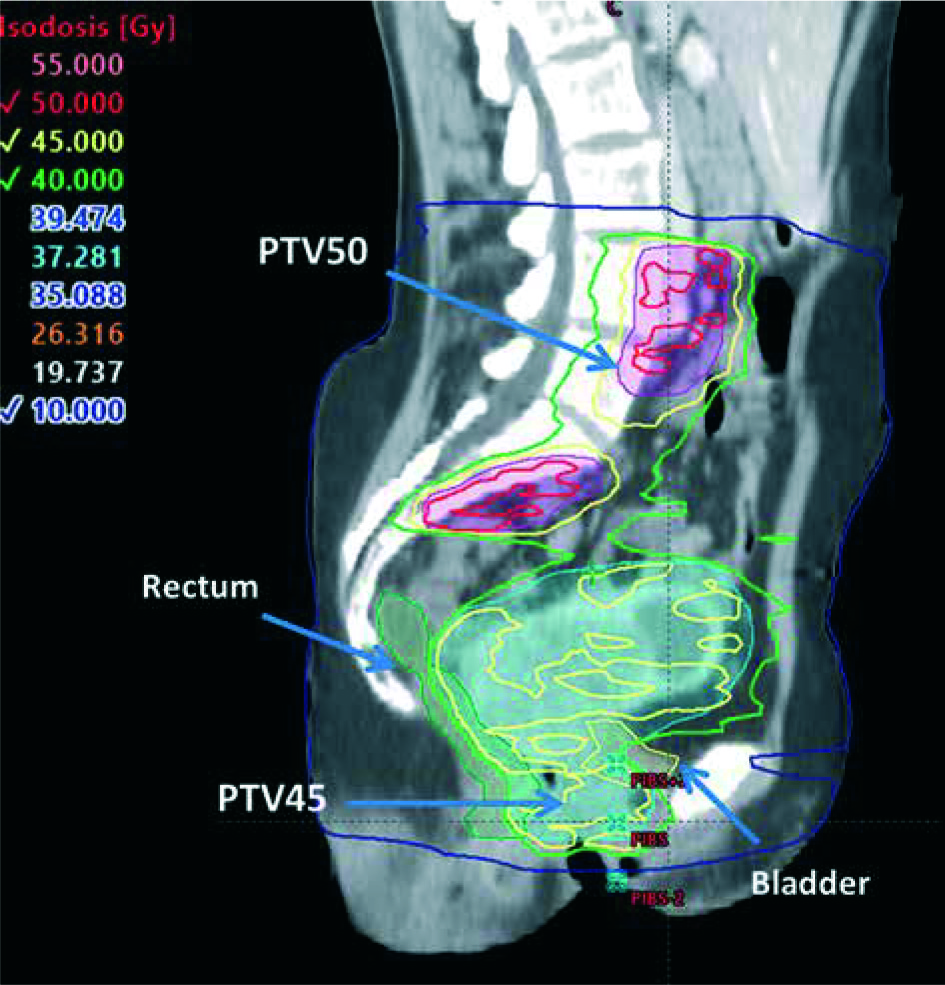
For EBRT, points are determined from the PIBS, which is selected as an anatomic landmark, since it is clearly visible on CT images. PIBS vaginal dose point is defined 2 cm posterior from this border in the sagittal direction, as illustrated in Figure 1. PIBS+2 is defined 2 cm up in cranial direction. PIBS–2 is analogously defined 2 cm down in caudal direction, both at the vaginal middle coronal plane.
Fig. 1
PIBS, PIBS+2 cm, and PIBS–2 cm in sagittal CT image corresponding to EBRT treatment. Image quality is limited by CT slice thickness of 3 mm
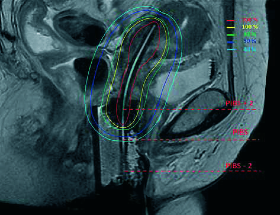
Regarding BT, three equivalent dose points are reported in an MRI para-sagittal reconstructed image. From the inferior-posterior corner of the symphysis, a tangent line is prolongated in the posterior direction until it crosses a catheter. This procedure determines the PIBS point. PIBS+2 and PIBS–2 points are defined in the catheter cranial and caudal direction, respectively. The determination of these PIBS points in BT is illustrated in Figure 2.
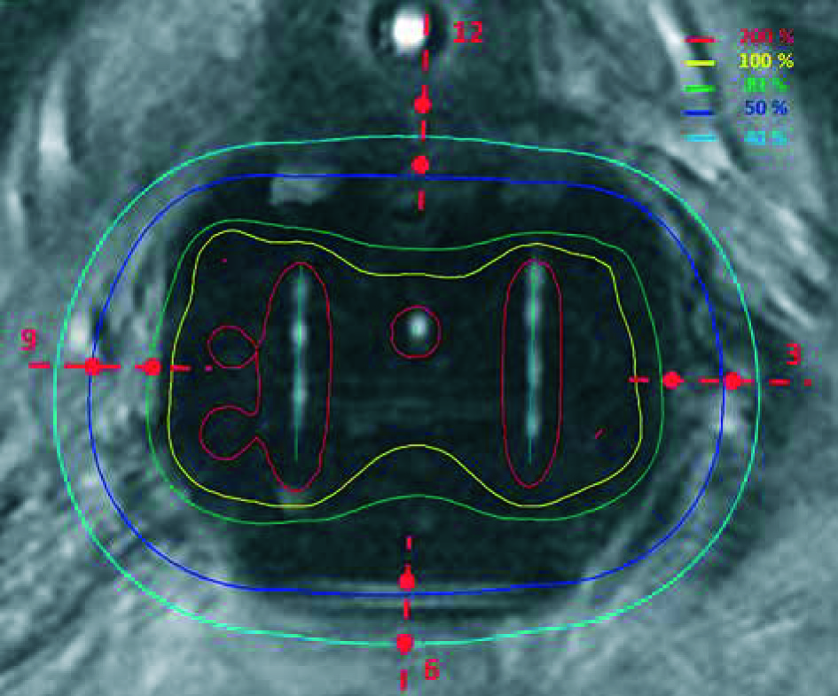
In addition, for BT, eight extra points in the upper vagina are reported at 3, 6, 9 and 12 o’clock orientations at the surface and 5 mm depth, as reported in Figure 3. To exactly determine these vaginal top points, one can focus on the MRI para-axial image containing the ovoids, where the source path inside the ovoids can be visualized. In this plane, points at the surface and at 5 mm depth of the left ovoid, at the central needle level (3 o’clock), and the equivalent points in the right ovoid (9 o’clock) can be defined. In the tangential line connecting both ovoids at the anterior part, the middle point (12 o’clock) and the point at 5 mm depth can be established. Similarly, the equivalent points in the posterior part (6 o’clock) and at 5 mm depth are also determined. With that procedure, the extra eight points on the MRI axial image for BT are defined.
Points located nearer than 5 mm from an active position were not included in the analysis. Also, some PIBS–2 located at the EBRT penumbra and out-of-field were excluded. Dose determination was obtained just by adding EBRT and BT, neither registration nor accumulation was performed between both image modalities.
Coefficient of variation (CV) was used in order to provide measurement of the data dispersion as a proportion to the mean [25]. For each of the P = 5 patients (p) and each of the n = 5 observers (o), two dose measurements M = 2 (m) in each point (i) were carried out. As mentioned above, each dose measurement was computed as the sum of the total EBRT dose and four times the BT dose per fraction in EQD2. We denoted these measurements as D(p, o, i, m). Inter-observer CV for each patient and dose point was defined as:
where σ(p, i) and D(p, i) are the standard deviation, and the mean between observers for a specific patient (p) and a dose point (i).
Our estimator for the inter-observer effect in each point was computed as the mean of the CV value for each patient in each point, i.e.:
Also, we wanted to estimate the intra-observer effect. In order to do that, the intra-observer CV for each patient, observer, and point were calculated as:
where D(p, o, i) corresponds to the dose average for one patient and observer at one point, and σ(p, o, i) is the standard deviation between the two measurements performed by each observer.
Our estimator of the intra-observer effect in each point was the mean among intra-CV values for each patient and observer in each point, i.e.:
Results
Maximum inter and intra-observer deviation in EQD2 are summarized for each patient and point in Tables 1 and 2, respectively. The maximum inter-observer deviation among all patients and all points ranged from 0.5 Gy to 24.1 Gy. The higher inter-observer discrepancies were found at 3 o’clock and at 6 o’clock. In case of the maximum intra-observer deviation, it ranged from 0.5 Gy to 14.2 Gy, with 12 o’clock and 9 o’clock as the points with higher deviation. In order to compare these differences and to understand their clinical importance, Table 3 reports mean doses for each point and patient. Maximum inter-observer deviation of absorbed dose per fraction for each point and patient normalized to D90 of the HR-CTV are reported in Table 4.
Table 1
Maximum inter-observer deviation for each point and patient. Missing values correspond to points closer than 5 mm to active source or located in the penumbra or out-of-field regions
Table 2
Maximum intra-observer deviation for each point and patient. Missing values correspond to points closer than 5 mm to active source or located in the penumbra or out-of-field regions
Table 3
Mean dose value for each point and patient. Missing values correspond to points closer than 5 mm to active source or located in the penumbra or out-of-field regions
Table 4
Maximum inter-observer deviation of absorbed dose per fraction for each point and patient normalized to D90 of the HR-CTV. Missing values correspond to points closer than 5 mm to active source or in the penumbra or out-of-field regions
The overall mean of inter- and intra-CV values according to Eq. 2 and Eq. 4 are presented in Table 5 for each point and contribution (BT or EBRT). Inter-/intra-CV (%) due to EBRT and EQD2-BT are in the range of 0.3-1.6 and 0.4-2.0, and 6.8-16.7 and 5.6-7.3, respectively.
Table 5
Inter- and intra-observer CV values in each point averaged among patients (P = 5) and observers (N = 5)
Discussion
First of all, it must be emphasized that this study did not pass any ethics review. This is a retrospective study, in which the obtained values did not affect the patient’s treatment. In fact, in our department, We have not yet adopted vaginal dose point reporting.
A limitation of the study was the use of different imaging modalities for planning, CT, and MRI, as these were established for planning in EBRT and BT, respectively. Moreover, the variability in some way included this lack of correspondence. Another limitation was the CT slice thickness, which could affect the determination of the pubis symphysis and consequently, the uncertainty of PIBS derived points. However, this could be improved by using a CT scanogram or CT scout view to program an acquisition, in which the symphysis could be clearly determined due to higher spatial resolution.
The choice of a single applicator type (interstitial Utrecht applicator) facilitated the determination of consensus. When tandem and ring applicators are used, the top of vagina points can experience additional variability, especially when the ring is not loaded laterally. In these cases, a similar study could be of interest to investigate such conditions.
All analyzed cases have different defined PTVs in EBRT, in an attempt to have a representative sample of cases at our institution as well as a higher gradient to compare to a case with unique PTV.
Inter- and intra-observer differences ranged from few gray to very high values, as 20 Gy. Larger differences corresponded to points close to an active source position, which had a high BT dose gradient or points located in the EBRT penumbra or out-of-field regions (some cases of PIBS-2). However, these points were excluded from the study.
A consensus between observers was established, and variations resulted from the use of different protocols, different applicators, or different imaging system were removed. However, there were relevant discrepancies not only between patients, as it has been previously reported [20,22], but also inter- and intra-observer discrepancies regarding the same patient. Moreover, intra-observer variations could be as large as inter-observer ones, when points are situated in a high gradient region. These discrepancies are due to some uncertainties, which are still quite difficult to correct in the protocol for the spatial determination of the points. For EBRT, the determination of the PIBS dose points requires to work in the CT sagittal plane passing through the symphysis. However, there was some variability in the precise determination of the previous plane and in the delineation of the tangent line to the symphysis by each observer. Similar problems appeared when defining PIBS points in MRI-BT images, since the limits of symphysis were not unequivocally defined. Finally, in the determination of the vaginal top points for BT, there was an uncertainty in the plane, where the eight vaginal top points were placed. This inter- and intra-observer variability had more significant consequences for points close to an active source position.
Despite the fact that the very high dose gradient points were removed from the evaluation, the remaining dose gradient existing in some points were already indicated as inter- and even intra-observers’ differences.
Our study described the collection of quantitative data on inter-observer and intra-observer variations and their impact on dose reporting for vaginal dose-effect calculations in cervical cancer brachytherapy. To our knowledge, this is the first study on reporting uncertainties for these relatively new dose metrics recommended by ICRU Report No. 89.
This mono-institution study had significant limitations due to the small number of patients, observers, and measurements per observer as well as statistical analysis. The aim of this study was to emphasize the potential discrepancies occurring in this new vaginal metrics, due to possible dose gradient and inter-observer determination and not establishing any kind of uncertainties. To analyze a larger sample from our institution or an extensive cohort of patients from different institutions would be a natural follow-up of this study.
Conclusions
Although a consensus between observers was established and variations due to the use of different applicators or different imaging systems were removed, there are still relevant inter- and intra-observer discrepancies. The aim of our mono-institutional study was to draw attention (in an almost qualitative way) to the variability when reporting dose at vaginal points and evaluating against tolerances and limits, due to potential local gradient location and inter-observer determination of points variability.


