
Purpose
Cervical cancer accounted for approximately 570,000 in 2018, becoming the fourth most frequent cancer in women [1]. Treatment depends on FIGO stage at diagnosis [2], performance status, and patients’ compliance.
Locally advanced cervical cancer (LACC), including stage IB3-IVA, is usually treated with platinum-based chemotherapy in association with external beam radiotherapy (EBRT), followed by brachytherapy (BT), often also called ‘interventional radiotherapy’ (IRT) [3, 4]. Magnetic resonance imaging (MRI) is the modality of choice in cervical cancer for both staging and response evaluation after concurrent chemoradiation therapy (CCRT) [2, 5].
Interventional radiotherapy in cervical cancer had advanced in the last ten years, using three-dimensional (3D) imaging and technological innovations [6-8]. Among imaging modalities, MRI is considered the most accurate imaging modality, compared with pathologic specimen, in the evaluation of the cervix tumor volume [9-12]. Several studies have proven that patient outcome improves using MRI in cervical cancer treatment [13-20]. MRI-guided IRT has been first proposed in 1992 [21], and since then has become the method of choice for planning IRT [22].
Image-guided IRT (IG-IRT) utilization is recently increasing; most of the centers use MRI-based planning at the first fraction, while few centers utilize MRI-based planning for each fraction [23]. It is due to the number of MRI scanner, increased effort demands, and a longer scan time.
The aim of this paper was to describe the MRI radiological workflow currently ongoing at our Institution. Furthermore, we provided a detailed MRI and IRT workflow, and a step-by-step approach in order to help, especially radiologists, in implementation of effective MRI-based IRT into general clinical practice.
Material and methods
Treatment procedure
Between July 2020 and April 2021, 65 consecutive patients with LACC underwent MRI-based IRT, following Gynecological Groupe Européen de Curietherapie-European Society for Radiotherapy and Oncology working group contouring and planning guidelines (Recommendations I and II by working group) [9, 24]. MR-safe applicators were used for all patients. Oncentra (Oncentra®Brachy treatment planning; Elekta, Sweden) system was applied to plan all treatments. Treatment was delivered using Elekta Flexitron afterloading machines with iridium-192 (192Ir) source.
Based on our protocol, interventional radiotherapy boost to high-risk clinical target volume (HR-CTV) and intermediate-risk CTV (IR-CTV) is performed after 45 Gy delivered with EBRT to low-risk CTV, IR-CTV, and HR-CTV, following GEC-ESTRO guidelines. The total IRT dose is 28 Gy to achieve a dose between 85 Gy to 95 Gy EQD2 (α/β = 10Gy) to D90 HR-CTV, and 14 Gy to IR-CTV in four high-dose-rate (HDR) fractions in order to achieve a D90 > 60 Gy EQD2 (α/β = 10Gy) [9].
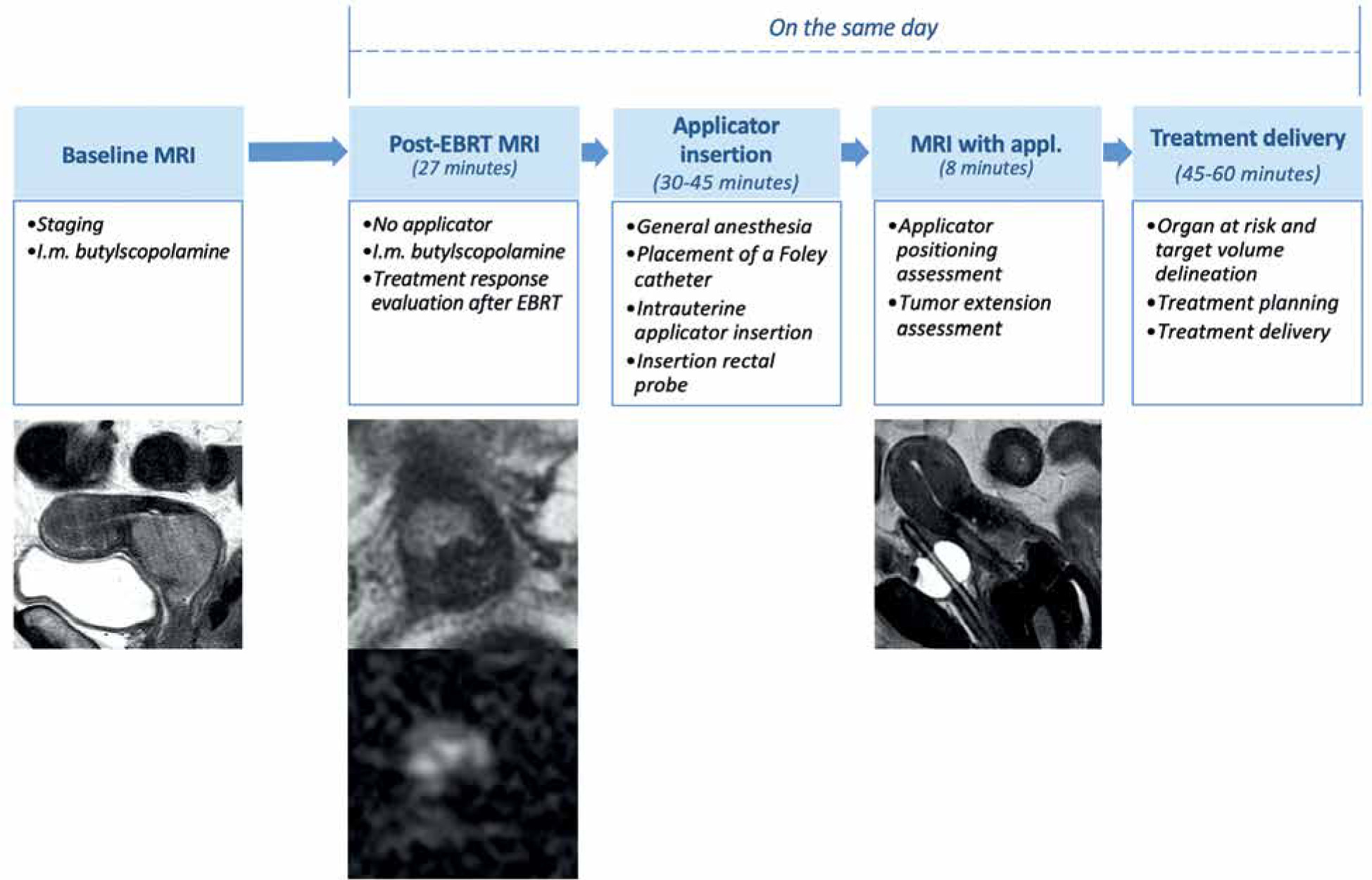
The treatment was arranged following an internal protocol: 1) baseline MRI (staging MRI), 2) EBRT, 3) post-EBRT pelvic MRI (post-EBRT MRI: day 1), 4) first applicator insertion (day 1), 5) pelvic MRI with applicators (post-applicator insertion MRI: day 1), 6) first and second fractions treatment planning, delivery, and applicator removal (day 1 and day 2), 7) second applicator insertion, third and fourth fractions treatment planning, delivery and applicator removal (day 10 and day 11). Time associated with delivery of first fraction was recorded. Details regarding the first insertion are presented in Figure 1. Computed tomography (CT) was performed for every IRT fraction to elaborate treatment planning for each treatment (1st, 2nd, 3rd, and 4th fractions). Planning CT images were acquired with 0.625 mm slice thickness and transmitted to treatment planning system (Oncentra).
Workflow planning
Our Institution’s MRI room is located close to the interventional oncology center (operative room and HDR-IRT bunker), taking 3-5 minutes to transfer patients between the two areas.
MRI protocol (for staging and evaluation post-EBRT, before and after applicator positioning)
Staging MRI and post-EBRT MRI were performed for all patients with a 1.5 T MR scanner (Echospeed Horizon and Infinity, General Electric Healthcare, GE), using a standard 8-channel phased-array body coil. MRI sequences included conventional MRI and diffusion-weighted imaging (DWI) sequences. Intra-muscular butylscopolamine (1 mg of buscopan, Schering) was administered to reduce bowel peristalsis. Conventional sequences included axial T2- and T1-weighted fast spin echo (FSE) sequence, high resolution FSE T2-weighted images in different imaging planes (sagittal/oblique axial and oblique coronal, respectively, perpendicular and parallel to the long axis of cervix). DWI sequence was performed on the same orientation of axial oblique FSE T2-WI, using single-shot diffusion-weighted echo-planar sequence, including two b-values (degree of diffusion weighting applied: 0 and 1,000 s/mm2). Axial T2-WI single-shot fast spin echo (SSFSE) and balanced steady-state gradient echo sequence (FIESTA, GE brand) were acquired up to the renal hila, to assess eventual lumbo-aortic lymphadenopathy and/or hydronephrosis. Detailed acquisition protocol is reported in Table 1.
Table 1
Magnetic resonance imaging protocol for evaluation of patients with cervical carcinoma after external beam radiotherapy (EBRT)
After applicator insertion, patients were re-scanned with 1.5 T MRI. Post-applicator positioning MRI was performed with fast imaging protocol, including only high resolution FSE T2-WI in three planes (axial, sagittal, and coronal) according to tandem applicator axis (Table 2). The aim of this scan was to assess correct positioning of the tandem and its’ position relatively to the cervix and/or the residual tumor, to accurately plan IRT treatment.
Table 2
Magnetic resonance imaging protocol for evaluation of patients with cervical carcinoma after EBRT
Applicator insertion
The positioning of the applicator was performed under general anesthesia. A Foley catheter was positioned into the bladder. After dilatation of the cervical canal, the applicator was placed using a transrectal US-guided procedure to ensure the correct position and reduce the risk of uterus perforation. The IRT applicator would serve as a canal for transportation of radioactive source.
The applicator must be MR-safe. Different applicator models are commercially available. It can be made of stainless steel, titanium, or plastic, and is composed of two main parts, including central tandem with ovoids or central tandem with ring. The central tandem is located inside the uterus canal, functioning as a stabilizer and means of passage of the radioactive source to the cervix and the uterus. The ovoids or ring are attached to the lower part of the tandem, and are usually allocated in the vaginal fornices leaning on the cervix. In case of parametrial involvement, interstitial IRT is recommended. Then, rectal probe is placed in the rectum to confirm the correct positioning of the implant.
Treatment planning
Organs at risk (OARs), IR-CTV, and HR-CTV were delineated as follows:
Organs at risk: Delineation of the rectum, bladder, sigmoid, and small bowel following their other contour.
Target volume delineation: IR-CTV carrying a significant microscopic tumor load, encompassed HR-CTV with a safety margin of 5-15 mm (with the exclusion of OARs). Amount of safety margin was chosen according to the tumor size and location, potential tumor spread, tumor regression, and treatment strategy.
HR-CTV included cervix + visible/palpable disease and gross tumor volume (GTV) – T2 bright areas [9]. Dose reporting was based on the total (EBRT + IRT) biologically equivalent dose in 2 Gy fractions (EQD2). Planning purposes were to deliver a minimum of 60 Gy to 90% isodose volume (D90), including IR-CTV, at least 85 Gy to D90 of HR-CTV, and more than 90 Gy to D98 of GTV preserving the established D2cc (the minimum doses calculated at the most irradiated 2cc volume) at OARs.
Focus on MRI role
Staging MRI and post-EBRT MRI: Staging and treatment response evaluation
MRI has shown high accuracy in cervical cancer evaluation, mainly for tumor size, assessment of deep stromal invasion, and parametrial invasion (specificity 97%, negative predictive value [NPV] 100%) [25, 26]. In addition, internal os involvement can be assessed on MRI with high sensitivity (90%) and specificity (98%).
At our Institution, response evaluation criteria in solid tumors (RECIST) version 1.1 are used to evaluate response to CCRT [27]. In case of complete response (CR) or partial response (PR)/stable disease (SD), patients are suitable for IRT. The standard method to assess the response to EBRT is to evaluate tumor size modification on post-EBRT MRI. Tumor size reduction is indicative of a good prognosis in LACC [28]. Full-thickness T2-WI low signal intensity is an indicator of reconstitution of cervical stroma integrity, configuring complete response to EBRT (NPV = 97%) [29]. However, hyperintense signal can be still visible on T2-WI, representing EBRT-induced inflammation, oedema, and necrosis [30]. DWI can improve detection of residual tumor, presenting as a focal hyperintense area on T2-WI and DWI, with corresponding hypointensity on the apparent diffusion coefficient (ADC) map [31, 32]. MRI evaluation of tumor response after therapy requires a comparative evaluation with staging MRI, in order to better interpret the imaging findings.
ADC can be helpful in differentiating residual tumor from post-radiotherapy fibrosis. Modifications of ADC value during and after EBRT have been associated with response to treatment and survival [33]. However, ADC value use is limited because of variable cut-offs reported in literature [34].
Concerning dynamic contrast enhancement (DCE) MRI, there is no consensus regarding its role for tumor response evaluation after EBRT treatment [34]. Some studies found that time-signal intensity evaluations are associated with treatment response [35, 36]. In our department, gadolinium-based contrast agent is not administered neither at staging MRI nor at post-EBRT MRI.
At our Institution, a standardized pro-forma reporting is used (Figure 2) for both staging MRI and post-EBRT MRI for correct staging of the tumor and evaluation of the response after EBRT, according to RECIST version 1.1. Moreover, every parameter and important sites of tumor extension are reported and compared between staging MRI and post-EBRT MRI.
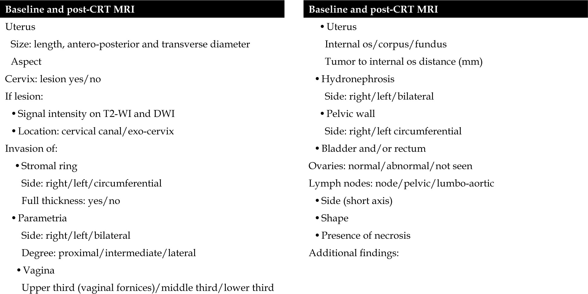
Mandatory findings include tumor diameter, cervical stroma invasion, parametrial invasion, vaginal invasion, uterus corpus/fundus invasion, hydronephrosis, relationship with adjacent organs (bladder/rectum), and lymph nodes.
The type of applicator is evaluated on case-by-case basis, and if post-EBRT MRI shows evidence of progressive disease or vesicouterine or rectouterine/rectovaginal fistula, a deep discussion is done in order to define the best personalized approach (Figure 3). On T2-WI, fistulas are seen as high signal intensity breach of the wall between cervix/vagina and the rectum or bladder. Sagittal plane is the most appropriate one for the detection of fistulas. These findings must be promptly reported and considered for next treatments planning.
Fig. 3
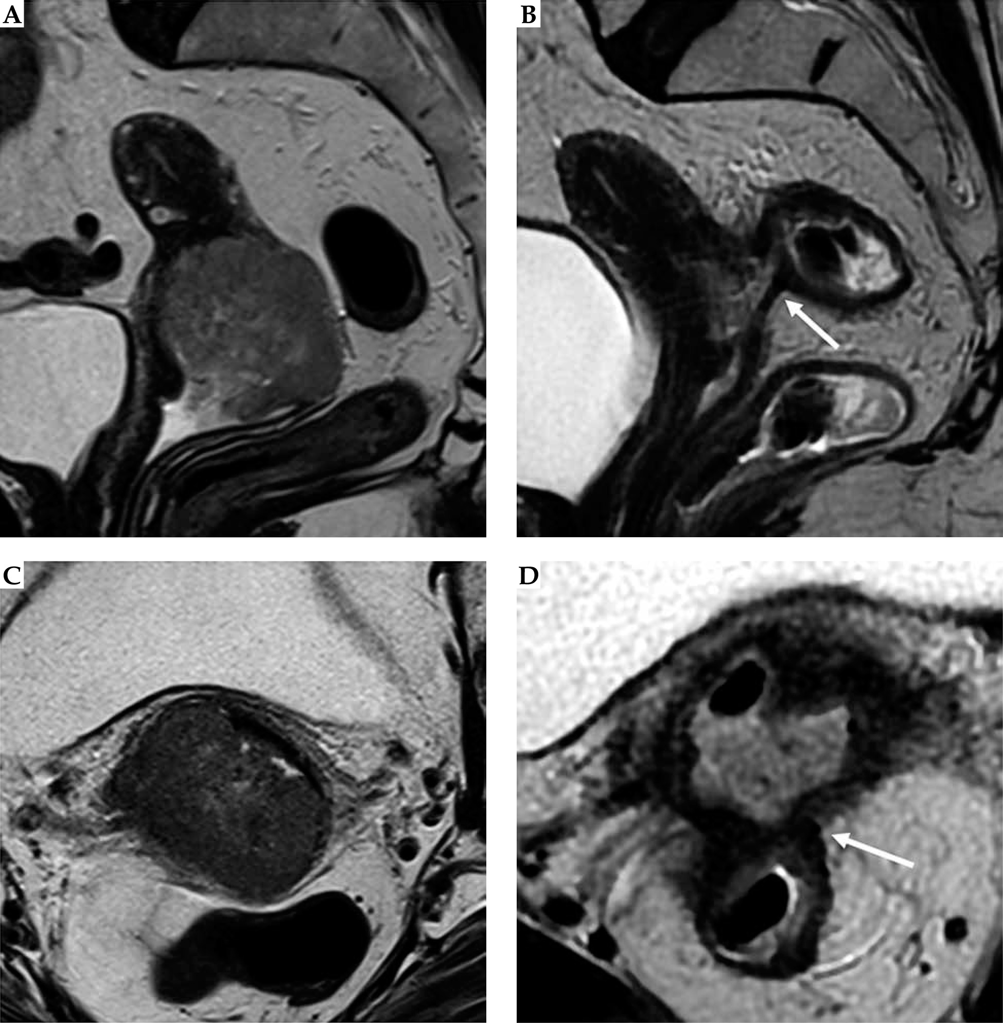
Post-external beam radiotherapy (EBRT) recto-vaginal fistula. Baseline and post-EBRT MRI in 72-year-old woman with squamous cervical carcinoma. At baseline MRI (A, C), T2-w sequences show the hyperintense cervical mass, extending to the upper third of the vagina, with maximum diameter of 50 mm (any plane). After concurrent EBRT (B, D), T2-w sequences show the presence of an hyperintense area in the posterior wall of the cervix and posterior vaginal fornix. Post-EBRT MRI presents a rectovaginal fistula (arrow)
CCRT can be a cause of ancillary findings, especially inflammatory ones regarding the rectum, sigmoid, and bladder. Radiologists must be aware of these because patients are often asymptomatic. Free fluid in the pouch of Douglas is a common collateral finding. Proctitis or colitis can be detected as mucosal thickening of the rectum or sigmoid colon.
Evaluation after applicator positioning
Post-applicator MRI serves to evaluate applicator positioning and provide support to IRT planning, in terms of tumor position and extension related to the applicator (Figure 4). Radiologists dealing with MRI-guided IRT are required to know specific parts of the applicator (ring, ovoids, tandem, etc.) and how to use the device. Surgical packing can be detected in vaginal cavity around the applicator, as low-signal intensity material, and should not be mistaken as hemorrhage or residual tumor. At our Institution, it is possible to perform endocavitary and interstitial IRT procedure. If residual tumor is detected, its’ relationship with the tandem/any vaginal applicator should be described. A structured report is currently in use at our Institution for post-applicator positioning MRI (Figure 5). This report includes useful findings for interventional radiation oncologists during IRT treatment planning. Firstly, type and position of the applicator considering location of tandem and ovoids or ring are described (Figures 6, 7). Secondly, relationships between the tandem and eventual residual tumor are defined (Figures 8, 9). In details, cranio-caudal extension of residual tumor and its’ location and maximum thickness are reported using a clockwise system (Figures 10, 11).
Fig. 4
Cervical cancer in a 55-year-old woman who underwent MR imaging with applicator. Sagittal (A), axial (B), and coronal (C) images, respectively, perpendicular and parallel to the plane of the applicator show tandem (arrow) in place. On axial plane (B), tumor (T) is located around the tandem from 7 to 1 o’clock (dotted line)
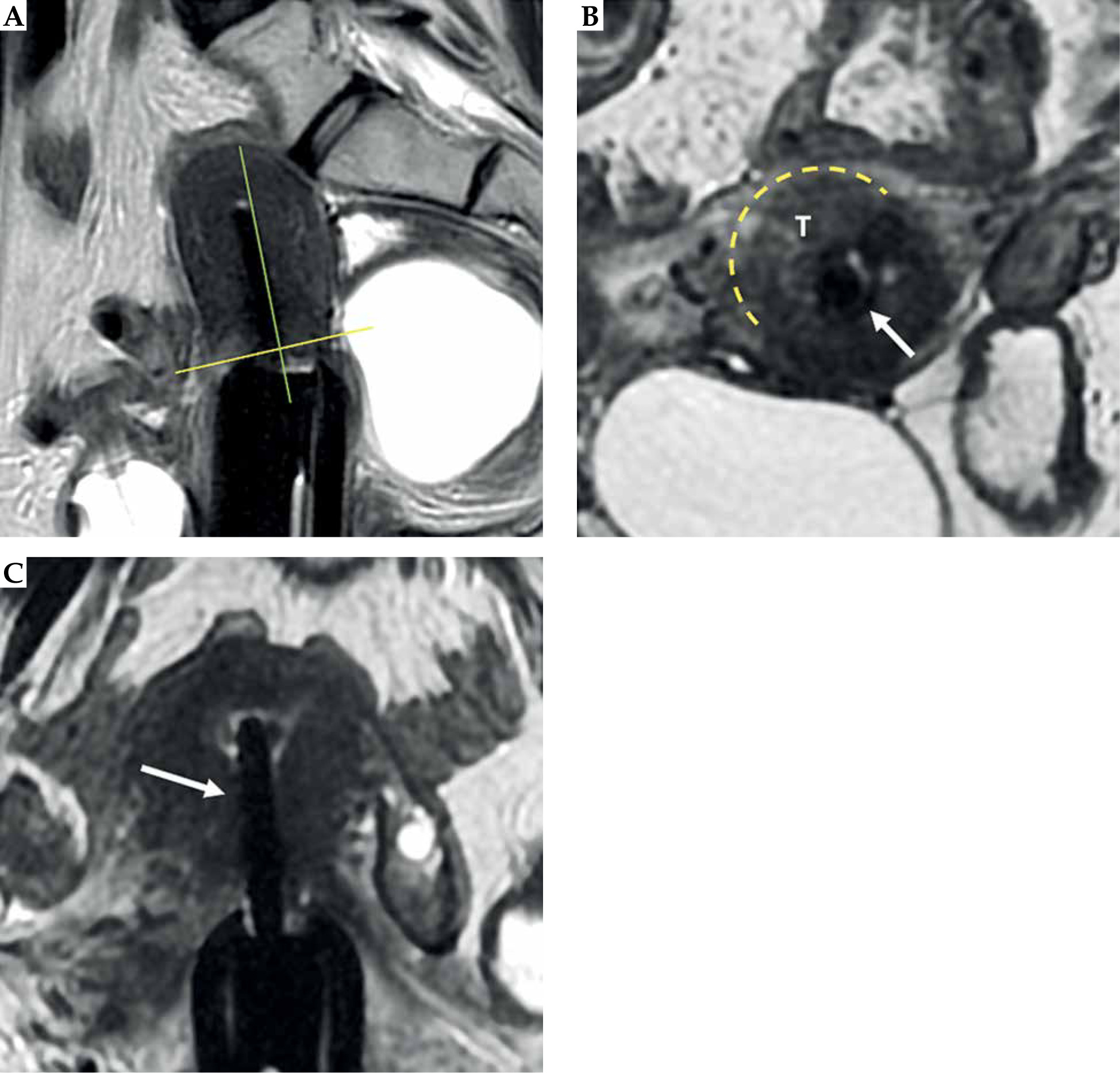
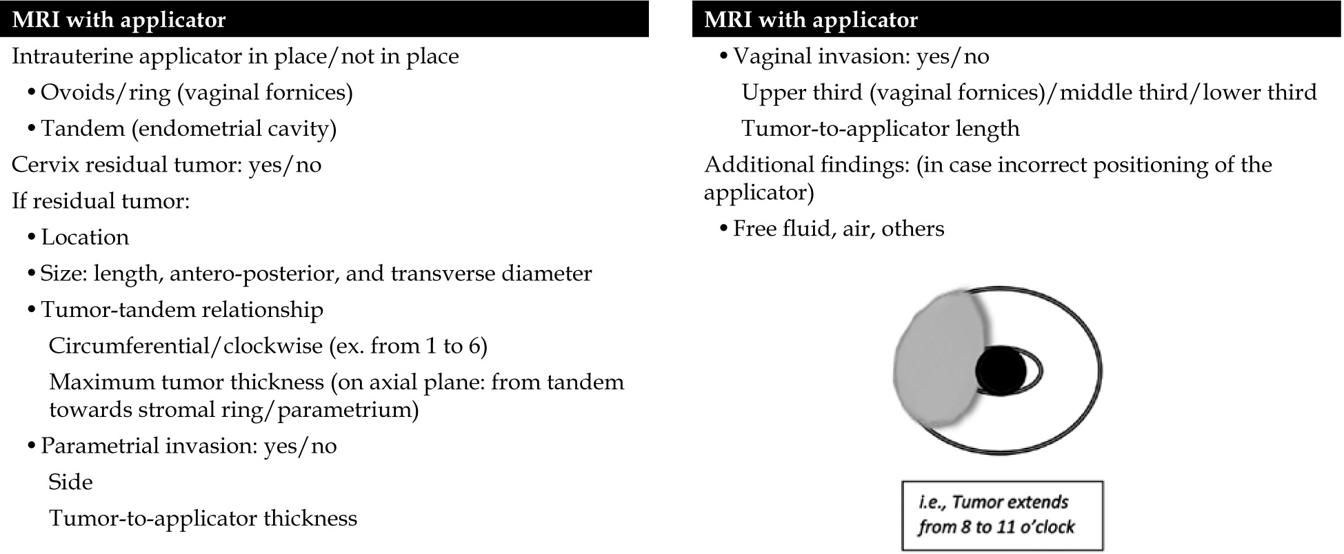
Fig. 6
31-year-old woman with squamous cervical carcinoma treated with EBRT. Post-external beam radiotherapy (EBRT) images (A, B) show reconstitution of low signal intensity of cervical stroma (arrows in B). C, D) Post-applicator MRI. Images show correct positioning of applicator within endometrial cavity (arrowhead) and ring in vaginal fornices (asterisk)
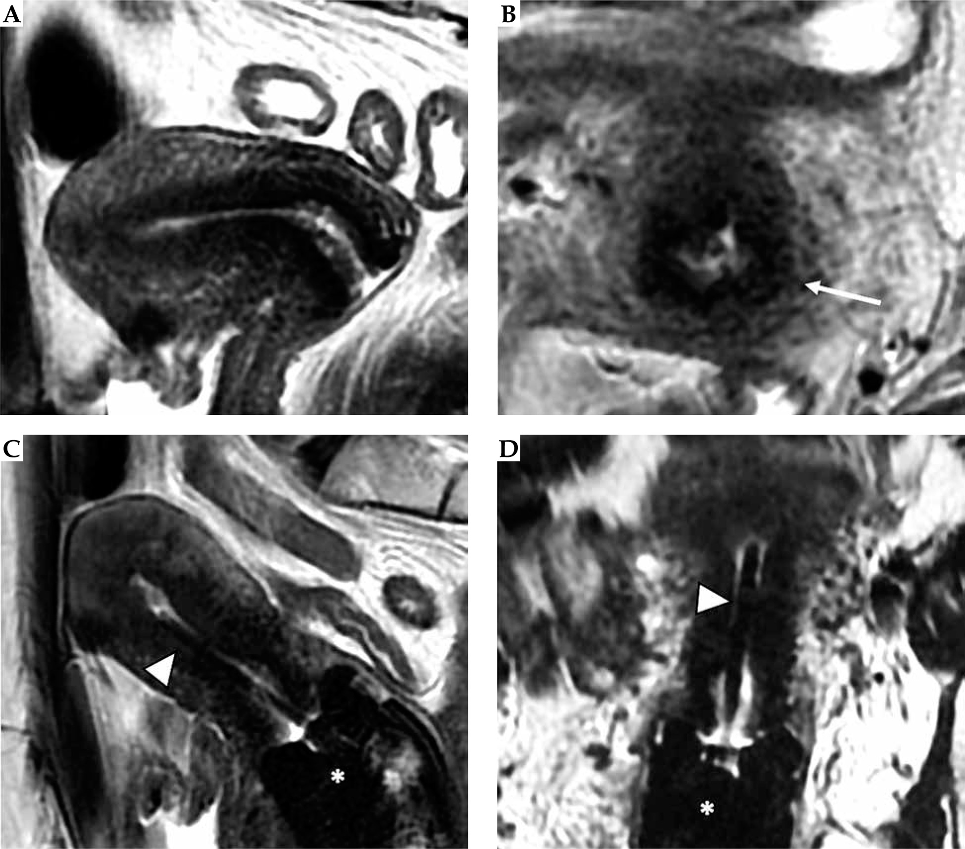
Fig. 7
59-year-old woman with squamous cervical carcinoma treated with external beam radiotherapy (EBRT). Post-EBRT images (A, B) show reconstitution of low signal intensity of cervical stroma (arrows in B). C, D) Post-applicator MRI. Images show correct positioning of applicator within the endometrial cavity (arrowhead) and ovoids in vaginal fornices (asterisk)
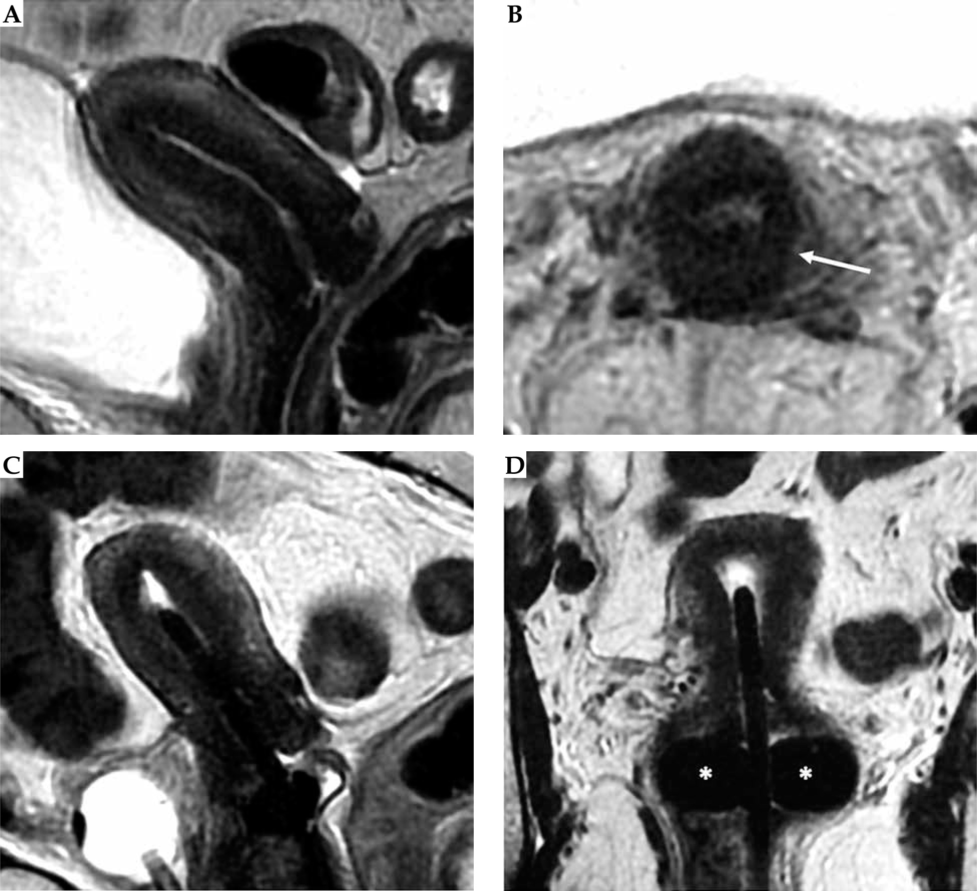
Fig. 8
Tumor maximum thickness: axial oblique T2-weighted FSE image perpendicular to the plane of the applicator (A) shows tumor extension within cervical stroma (arrow with maximum tumor extension (dotted line) from the tandem (arrowhead) within the cervical stroma at 9 o’clock) (B). Schematic illustration of the tumor maximum thickness (C)
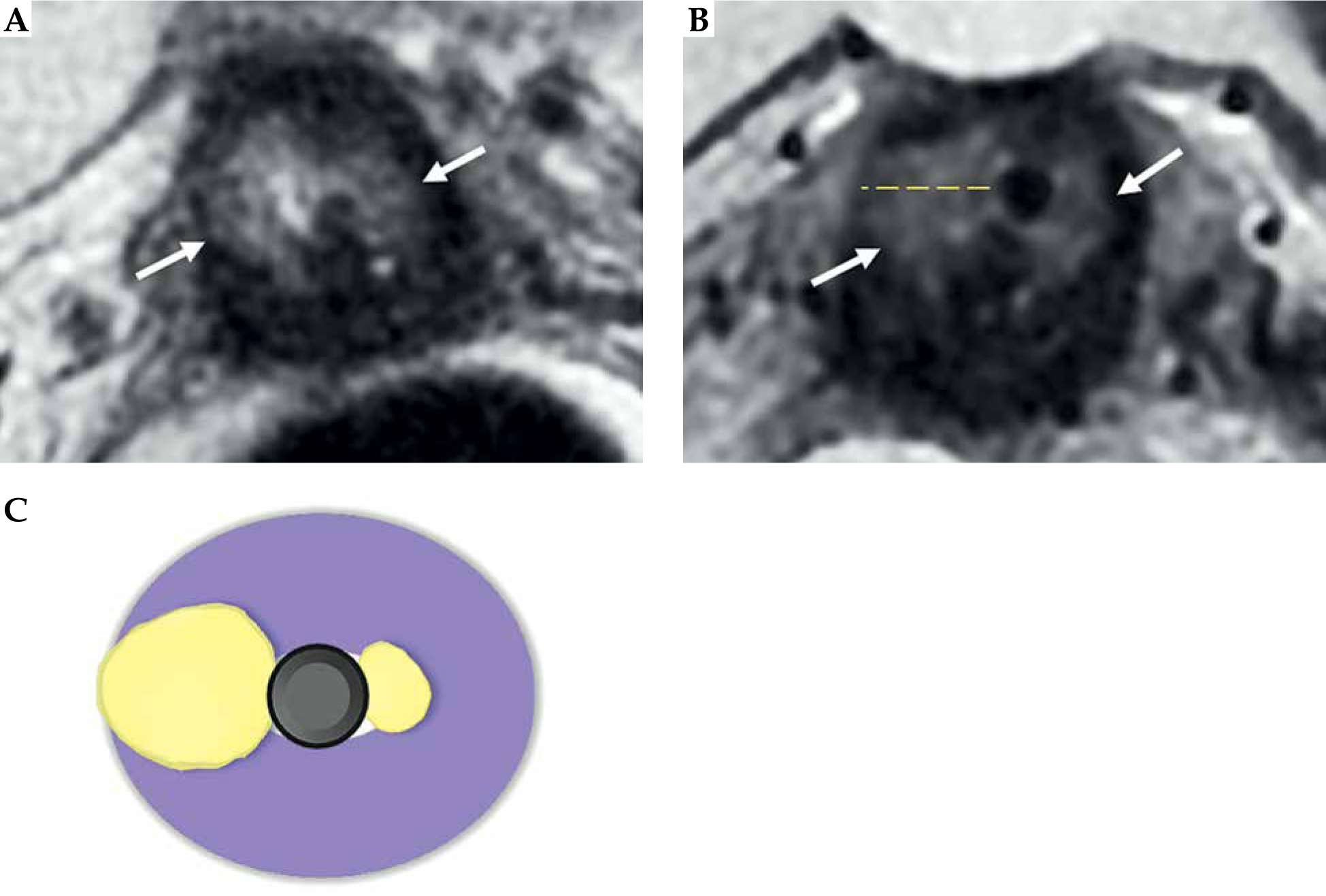
Fig. 9
Maximum tumor length: coronal oblique T2-weighted FSE image in the plane with the applicator (A) shows maximum tumor length (dotted line) from the ring (*), along with the tandem (arrow) (B). Schematic illustration of the tumor maximum thickness (C)
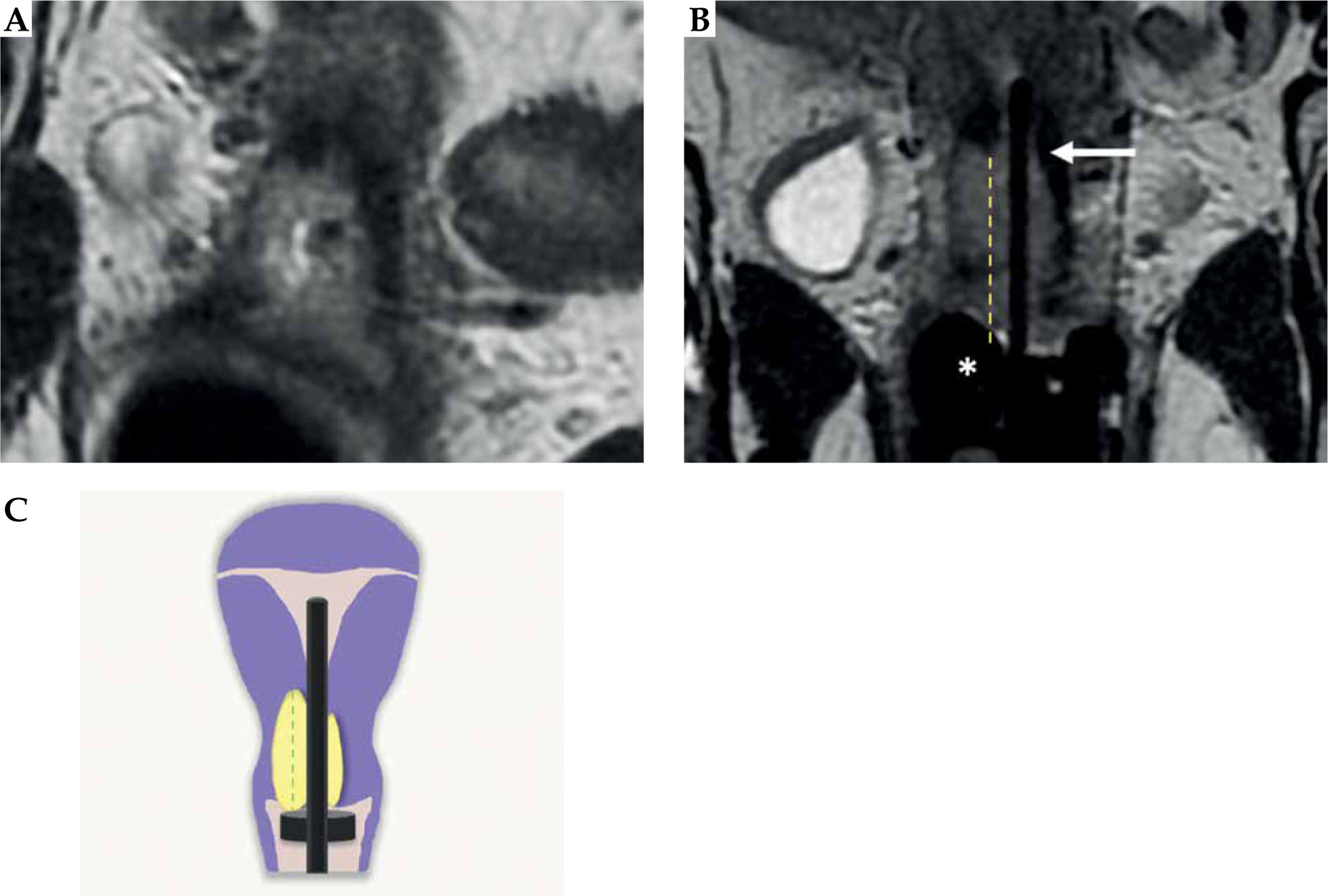
Fig. 10
34-year-woman with squamous cell cervical carcinoma. Post-external beam radiotherapy (EBRT) axial oblique T2-weighted image (A) indicates high signal-intensity residual tumor (T) extending in the right and posterior parametria. Post-applicator MRI (B-D) shows the relationship between the applicator and the residual tumor. In this case, interstitial needles (arrows in C) were placed to cover parametrial extension of the tumor
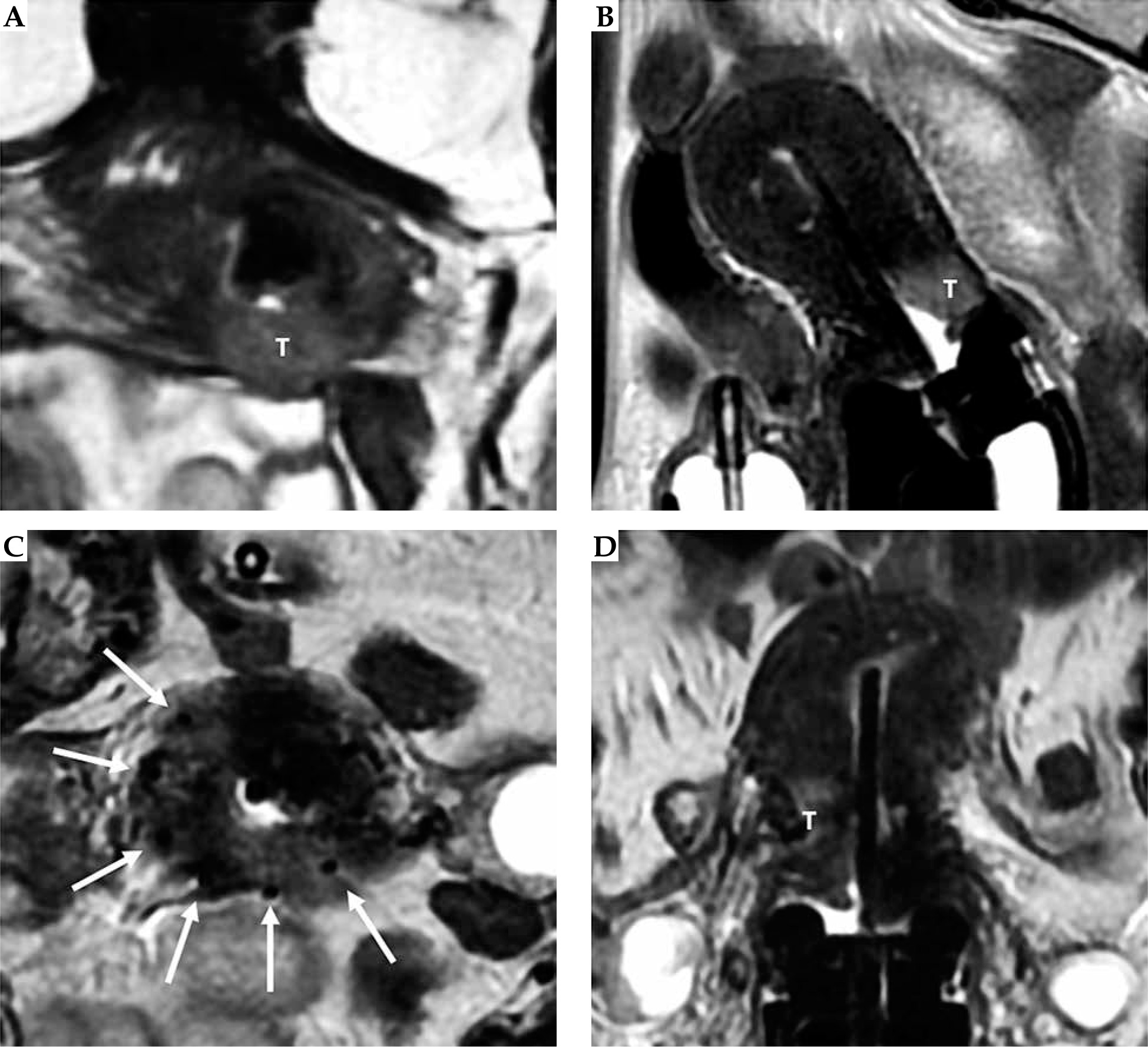
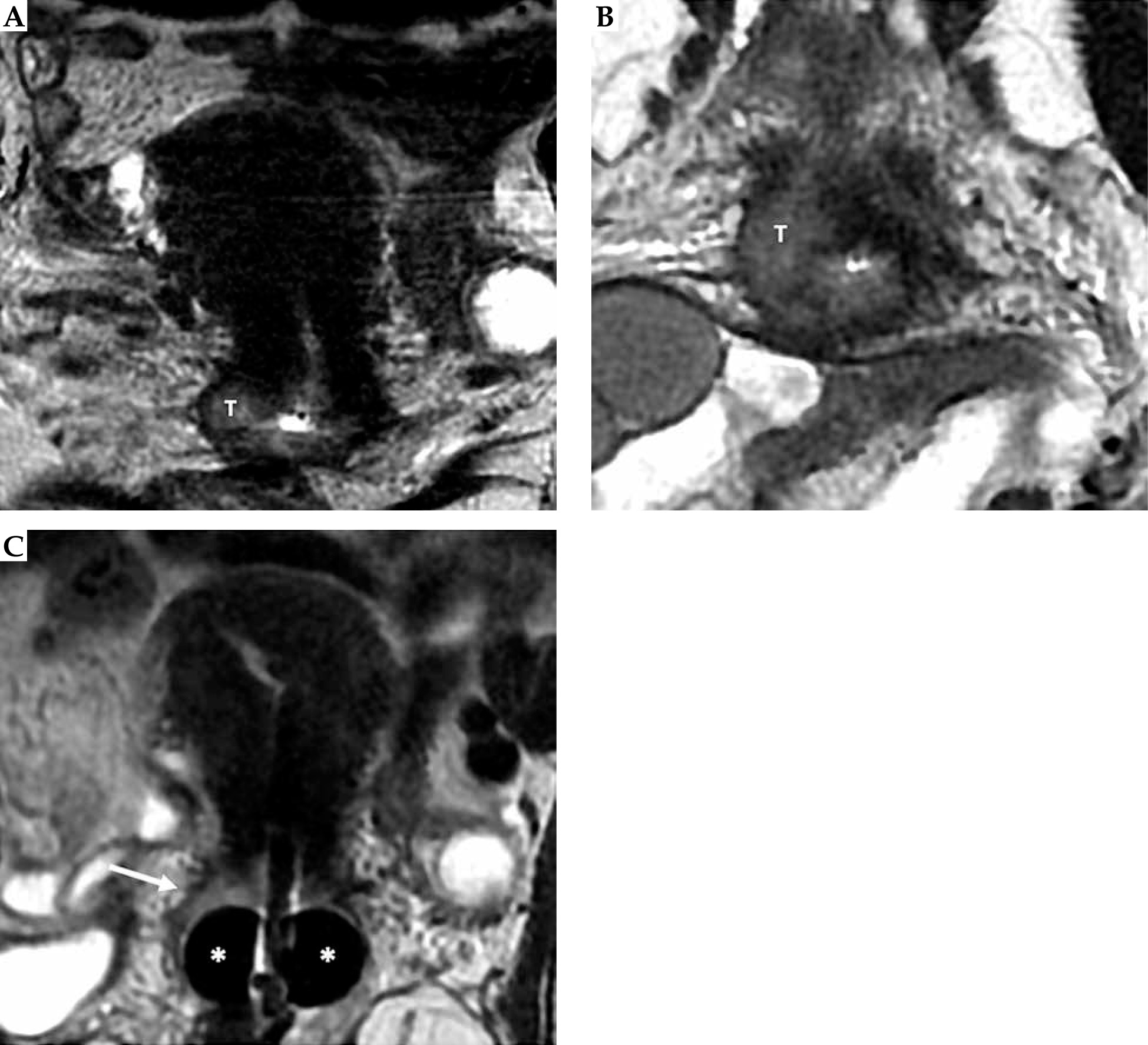
Fig. 11
55-year-old woman with squamous cell cervical carcinoma. Post-external beam radiotherapy (EBRT) coronal and axial oblique FSE T2-weighted images (A, B) show high signal-intensity residual tumor (T) in the right stromal portion and in the right vaginal fornix. Post-applicator coronal T2-weighted image (C) presents the relationship between the applicator and the residual tumor (arrow)
After EBRT, cervical and uterine tissues change after radiation, and for this reason, a uterine perforation can occur. US-guided insertion and post-applicator MRI enable accurate detection of this complication [37, 38].
On MRI images, the adjacent OARs are identified [9, 10]. At our Institution, GTV, HR-CTV, IR-CTV, and OARs are segmented by radiation oncologist, who, whenever necessary, reviews images with the radiologist [9, 10]. After plan optimization approving, procedures are applied:
Then, the treatment is delivered.
Conclusions
The workflow currently ongoing at our Institution was presented. 1.5 T MRI is performed before and after cervix applicator insertion, with unquestionable advantages. First, MRI is the imaging modality of choice for staging and treatment response assessment due to high accuracy in cervical cancer evaluation (tumor size, assessment of deep stromal invasion, and parametrial invasion). After concurrent EBRT, MRI with DWI provides accurate evaluation of treatment response. Furthermore, MRI scan after applicator insertion is essential for the evaluation of correct cervix applicator insertion, and provides accurate assistance for IRT treatment planning in order to achieve personalized approach.


