
Purpose
In surface high-dose-rate (HDR) brachytherapy, superficial lesions are irradiated by highly radioactive sources for short periods of time using an afterloader unit. Accurate dose delivery requires positional accuracy of source positions within 1 mm [1]. For large or irregular treatment surfaces, the treatment method of choice is to cover the cutaneous lesion by flexible flap applicators, in which radioactive seeds are introduced [2]. The clinical target volume (CTV) and/or planning target volume (PTV) are delineated on the patient’s skin using suitable markers [3]. The treatment area, applicators, and surface markers are imaged during a simulation procedure in order to inform the treatment plan.
High-dose-rate brachytherapy skin markers have been developed for visibility on computed tomography (CT), which is the most common imaging modality for surface brachytherapy. Commercially available surface brachytherapy markers (e.g., CT-SPOT marker [4]) consist of plastic wires of 2 mm diameter, which can be cut to the required length and combined to delineate the edges of target volumes. They are taped on the assumed lesion and margin borders on the skin by means of adhesive wings on each side of the wire. Due to the surface marker importance in the treatment planning procedure, a cross-section of these wires on CT simulation images is contoured in the treatment planning system (TPS) using a circle corresponding to their diameter [5].
Magnetic resonance imaging (MRI) offers better soft tissue contrast than CT, and can detect palmar and plantar fibromatosis [6, 7], facial basaliomas [8] as well as discern cutaneous basal cell from squamous cell carcinomas of the head and neck [9]. With its superior soft tissue differentiation, MRI may individualize dose prescription depth, as opposed to the currently set standard of 3 mm for typical lesions [10]. Despite these advantages, MRI has not been historically utilized for surface HDR brachytherapy, because its surface applicators and skin markers are not visualized by common clinical MR sequences. However, recently, Freiburg flap (FF) applicators were detected using optimized pointwise encoding time reduction with radial acquisition (PETRA) MR sequences [11], owing to their minimal repetition time (TR) and echo time (TE) [12]. PETRA MR images were also used to generate HDR surface brachytherapy treatment plans, which were comparable to CT-based plans [13, 14]. Furthermore, T1-weighted volumetric interpolated breath-hold examination (VIBE) MR sequences, which can also employ a very low TR and TE, have simultaneously visualized flap applicators and human skin [15]. The Dixon technique producing water-only and fat-only images by combining acquisitions for which water and fat are in-phase or out-of-phase [16] is applicable on VIBE sequences. Dixon VIBE is widely employed in diagnostic radiology and for radiotherapy MR simulations, and has recently demonstrated the potential to identify surface pathologies, such as palmar fibromatosis [17].
Given the opportunity presented by these developments for skin brachytherapy treatment planning relying on MRI only, identification of skin markers defining target edges on MR images would be required. However, plastic materials composing the skin marker wires for CT simulations produce no signal for any MR sequences. On MRI, such materials can only be indirectly detected by their lack of signal when surrounded by biological tissues [18], but cannot be distinguished from background air if placed on a surface. A successful skin marker for MR-based treatment planning should provide positive signal on MR images.
Standard MR surface markers are based on small quantities of fluids or gels (e.g., cod liver oil) encapsuled in small watertight packets, which can be stuck on a surface [19]. These materials have a high hydrogen content, providing high signal intensity on most MR sequences. Modern dedicated commercial MR marker solutions, such as MR-SPOT [20], include adhesive packets or tubes of dimensions between a few mm to 5 cm, and are intended to determine a specific area of interest. However, they cannot continuously trace the borders of a large or geometrically complex area, as it is necessary for target delineation in skin brachytherapy. Using multiple common MR skin markers is impractical for this purpose, and their shape and dimensions may compromise the placement of surface brachytherapy applicators. The ideal skin brachytherapy marker for MR simulations would resemble the surface markers used during CT simulations, and be visible primarily on MR and optionally on CT images. A flexible wire shape with comparable diameter to the current CT surface markers and adjustable length would allow for minimal modifications of the patient preparation procedure, and for straightforward implementation of the standard TPS marker contouring algorithms on MR images.
In this work, we investigated the potential of solid silicone rubber tubing as an alternative skin marker for MR-only surface HDR brachytherapy. Commercial tubes were tested on an anthropomorphic phantom, a healthy volunteer, and three palmar fibromatosis patients. Two different tube sizes were assessed for detectability on the obtained MR and CT images and contourability with a clinical TPS. For the optimally sized tube, its signal intensity values in terms of Hounsfield units (HU) on CT images as well as its signal intensity in relation to muscle tissue on MR images were determined.
Material and methods
Subjects of this study included an adult full human body phantom (True Phantom Solutions, Windsor, Ontario, Canada), a consented 25-year-old healthy female volunteer, and three consented patients (age range, 57-73 years) with palmar fascial fibromatosis (Dupuytren’s contracture). Solid silicone rubber tubes of 2 mm or 3 mm diameter, obtained from an e-commerce platform (UXCell, Hong Kong, China) were cut into pieces using scissors, and were attached on the left palm of the anthropomorphic phantom and healthy volunteer using adhesive tape (Figures 1-3A, 5A). The phantom and volunteer were imaged with the 2 mm tube in the first session, and with the 3 mm tube in the second session. The affected hand of each Dupuytren’s contracture patient was palpated by the treating physician to define CTV. Then, PTV was defined by expanding CTV on the palmar surface by a 2 cm margin. For the first patient, an adhesive CT-SPOT marker (Beekley, Connecticut, USA) was placed on the patient’s palm and two last fingers to delineate the PTV. In addition, 2 mm diameter silicone rubber tubing pieces were taped on the patient’s palm next to the CT-SPOT marker along its length (Figure 4E). For the next two patients, tube pieces of 3 mm diameter were taped on CTV borders, while pieces of CT-SPOT marker were placed on PTV borders (Figures 6E, 8E). FF applicators (Elekta, Stockholm, Sweden) were fastened on the selected inner hand of each subject.
Fig. 1
A) Left hand of an anthropomorphic phantom with a 2 mm diameter silicon tube taped on its palm. B) The phantom hand with FF applicators affixed on the phantom’s palm. C) Dixon OP, D) Dixon fat, and E) PETRA axial images of the phantom hand, with blue circles indicating the detected tube position. F-H) 3D reconstructions of the corresponding top images with the tube contour produced by TPS marked in blue
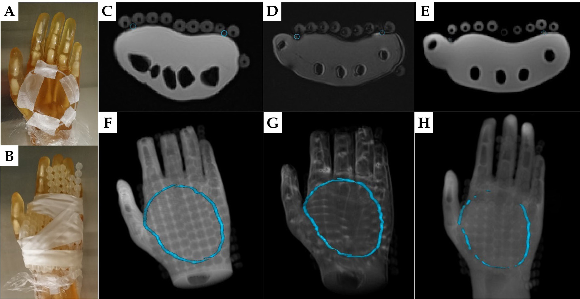
Fig. 2
A) The 3 mm diameter silicon tube taped on the left palm of the anthropomorphic phantom. B) FF applicators fastened on the phantom’s palm. C) Dixon OP, D) Dixon fat, and E) PETRA axial images of the phantom hand. Green circles indicate the tube position. F-H) 3D rendering of the above axial images with TPS drawn tube contour marked in green
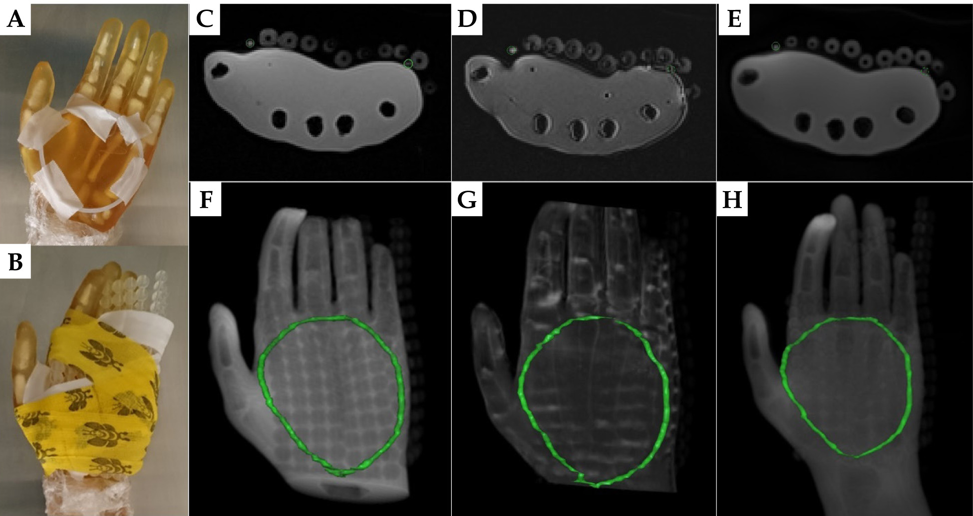
Fig. 3
A) Hand of a healthy female volunteer with taped silicon rubber tubing pieces of 2 mm diameter. B) Subject position in the scanner after wrapping FF applicators around her hand. C) Dixon OP, D) Dixon fat, and E) PETRA images of the volunteer in the originally acquired axial (left), and reconstructed sagittal (middle) and coronal (right) orientation. Red crosshairs show the tube position in all views. Red arrows indicate an additional tube location on the axial images
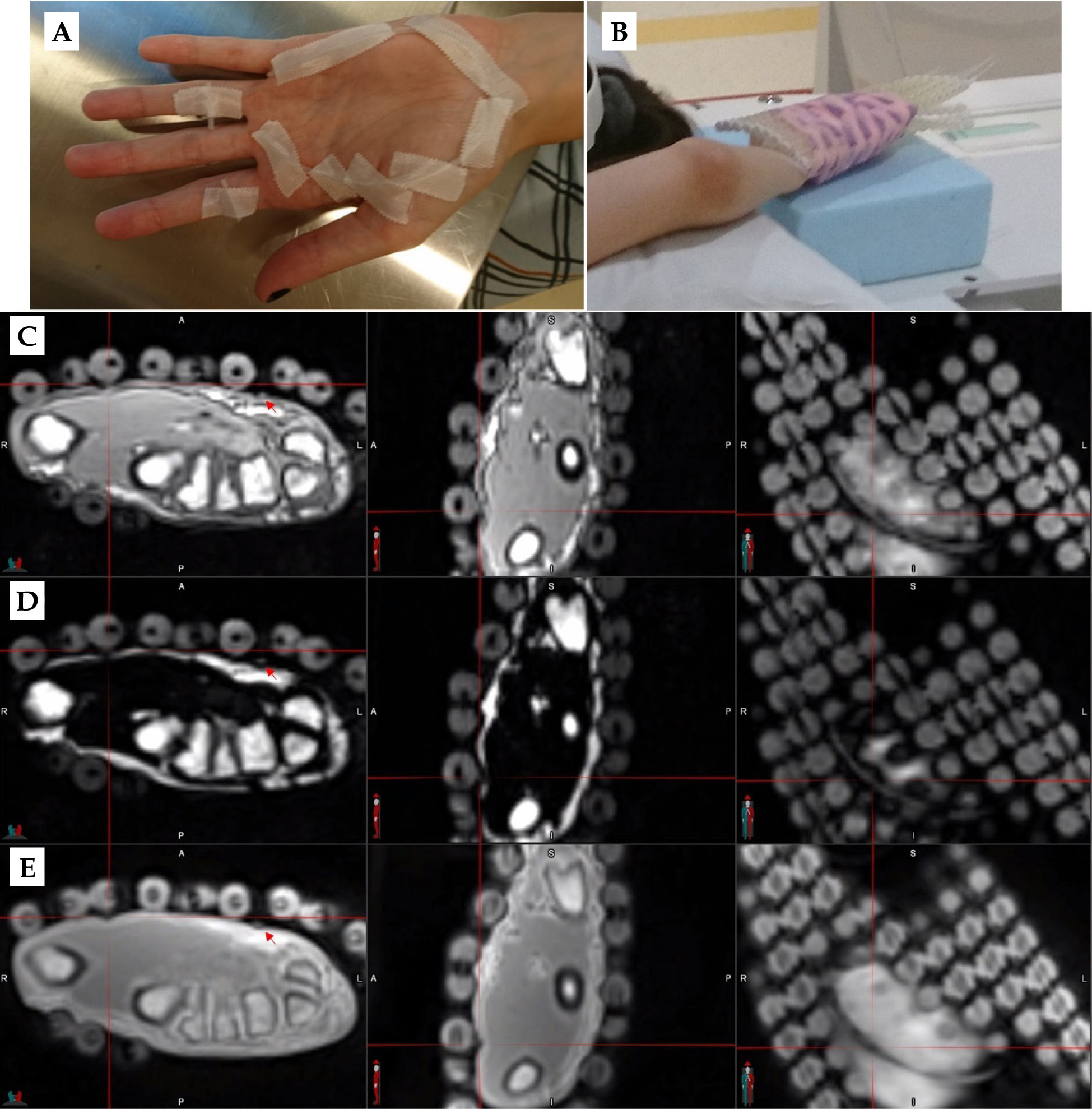
Fig. 4
A-D) Axial images of palmar fibromatosis patient #1, with the detected 2 mm silicon tube marked by dashed circles. A) CT, B) PETRA, C) Dixon fat, and D) Dixon OP. E) Patient’s hand with a 2 mm silicon rubber tube taped on top of a CT-SPOT marker wire. F) 3D reconstruction of CT images with the contour of the CT wire in blue. G, H) 3D rendering of PETRA and Dixon fat images, respectively, with the tracked tube contour in color. I) 3D reconstruction of the Dixon opposed-phase images with the delineated tube contour in red and superimposed CT wire contour in blue. All contours were drawn in a clinical TPS
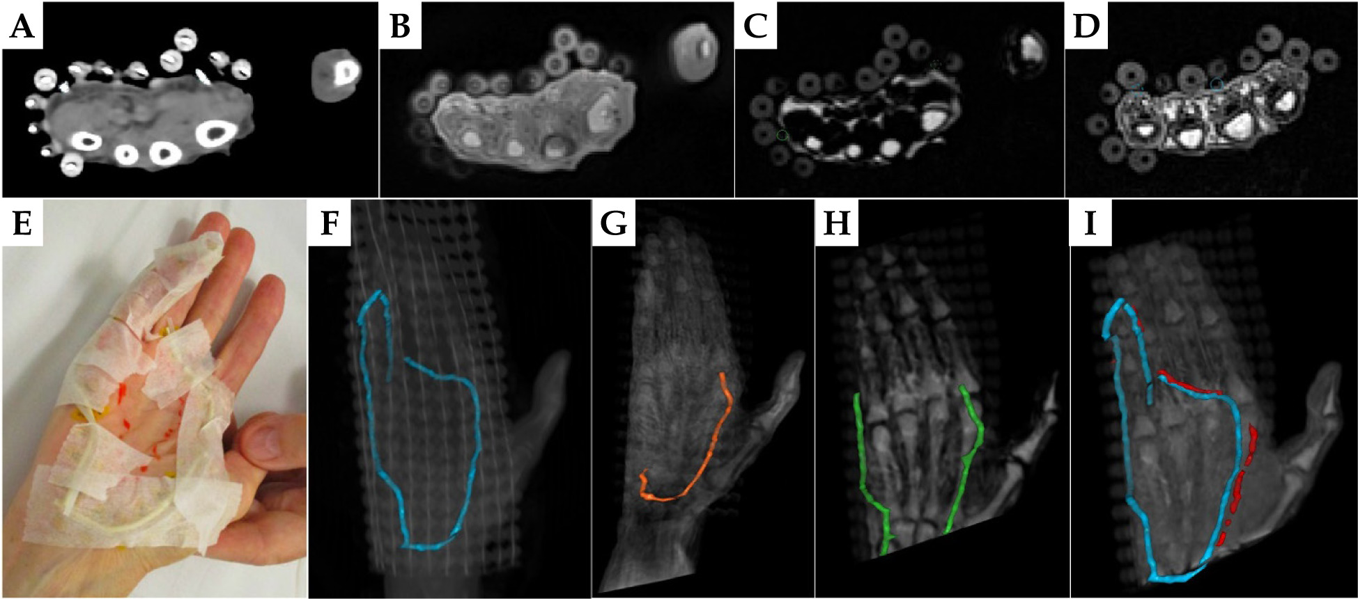
Fig. 5
A) 3 mm diameter silicon tube taped as a loop on the left palm of a healthy volunteer. B) FF applicators tightly wrapped over the palm. C) Dixon OP and D) Dixon fat reconstructed axial views of the coronally acquired VIBE sequence. E) Axial PETRA images. The yellow or red circles show the positions of detected tube cross-sections. F-H) 3D MIPs of Dixon OP, Dixon fat, and PETRA images, respectively, with TPS tracked tubing in yellow or red
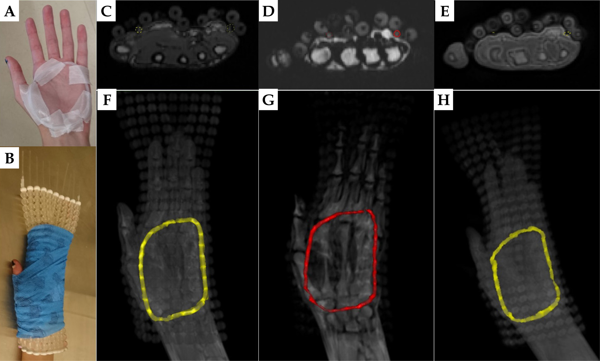
Fig. 6
Example axial images of palmar fibromatosis patient #2. A) CT, B) PETRA, C) Dixon OP, and D) Dixon fat. Colored circles mark the detected 3 mm tube. E) The tube taped on the CTV borders on the patient’s palm and three fingers. 3D MIPs of F) CT, G) PETRA, H) Dixon OP, and I) Dixon fat series containing TPS drawn colored tube contours
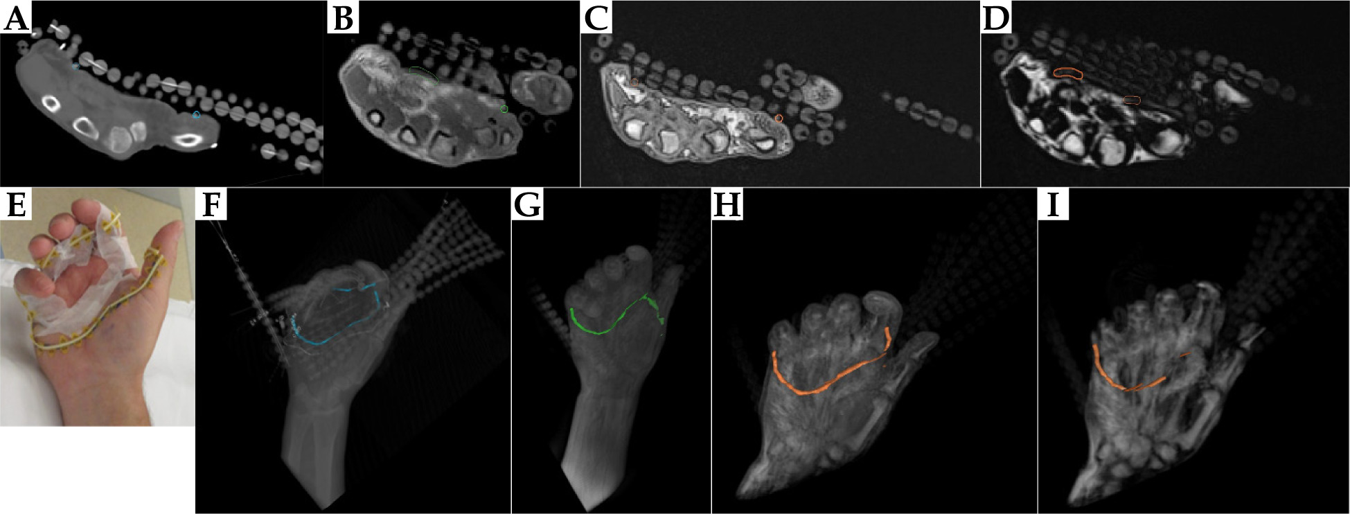
Fig. 7
Axial A) CT, B) PETRA, C) Dixon OP, and D) Dixon fat images of palmar fibromatosis patient #3, with E) CTV delineated by a 3 mm silicon rubber tube and PTV by a CT-SPOT wire. Detected tube cross-sections are circled on the top axial images, and TPS reconstructed tube contours are displayed with the corresponding color on 3D MIPs of F) CT, G) PETRA, H) Dixon OP, and I) Dixon fat series in the bottom panel
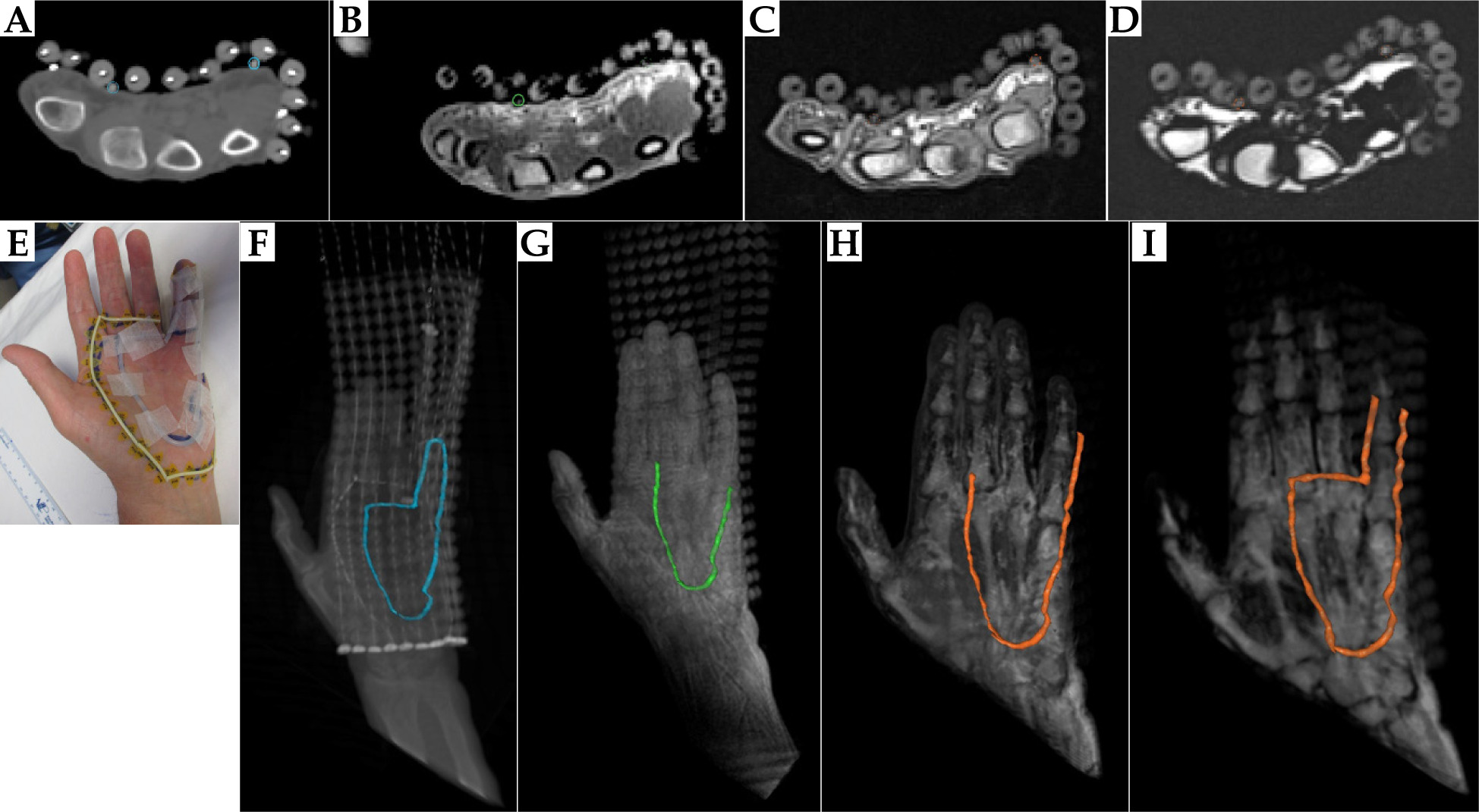
Fig. 8
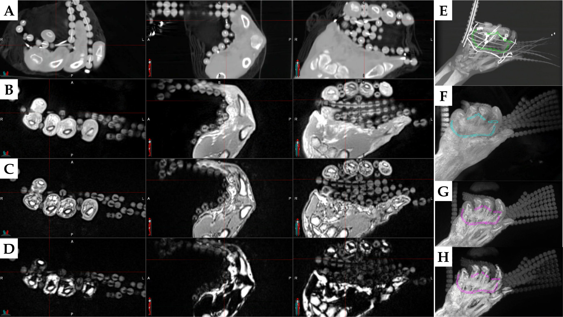
Left panel: Axial, sagittal, and coronal views of the hand of palmar fibromatosis patient #2 on A) CT, B) PETRA, C) Dixon OP, and D) Dixon fat with red crosshairs pointing on a piece of the 3 mm diameter tube taped on the third finger. The right panel contains the MIP of each series: E) CT, F) PETRA, G) Dixon OP, and H) Dixon fat, with MIM drawn tube contours in color
MR scans with empty applicator catheters were performed at a 3T MAGNETOM Vida (Siemens Healthcare, Erlangen, Germany). Subjects laid supine with their hand above their head, supported by a block, with the palm facing up (Figure 3B). Images were obtained using a Flex Small 4 or Flex Large 4 coil over the affected hand and a biomatrix (BM) Spine 32 coil on the scanner couch. A 3D T1-weighted Dixon volumetric interpolated breath-hold examination (VIBE) sequence (repetition time (TR) = 4.6 ms, echo time (TE1) = 1.62 ms, TE2 = 2.77 ms, flip angle = 9°, bandwidth = 710 Hz/pixel, field-of-view = 320 × 320 mm2, 0.9 × 0.9 × 1.2 mm3 voxels), and a 3D pointwise encoding time reduction with radial acquisition (PETRA) sequence (TR = 3.32 ms, TE = 0.07 ms, flip angle = 6°, bandwidth = 400 Hz/pixel, field-of-view = 317 × 317 mm2, 0.9 × 0.9 × 0.9 mm3 isotropic voxels), were acquired in axial orientation. For the volunteer session with 3 mm tubing, the VIBE sequence was repeated in coronal orientation to ensure full tube and applicator coverage. The patients additionally underwent a CT examination as per standard of care (slice thickness = 1.25 mm, large field-of-view, 120 kVp, 250 mAs), with metal wires introduced into applicator catheters.
The obtained PETRA and Dixon images of all subjects were reviewed for tube conspicuity. Image series considered best for tube identification were uploaded to Oncentra Brachy TPS (Elekta Brachytherapy, The Netherlands). Silicone rubber tubes were reconstructed using TPS, with a custom window and level configuration for axial images of each MR series. In the patient cases, the CT marker was also contoured on the axial CT images according to current clinical practice. In addition, the 3 mm diameter tube that was spatially separated from the CT-SPOT marker on MR and CT series of the last two patients, was contoured in MIM 7.2.7 software (MIM Software Inc., Cleveland, Ohio, USA) using a 3D thresholding sphere of 2.63 mm diameter on original axial images, consulting also the other two planes of 3D acquisitions. To exclude air from the contours, a threshold value of 40, 100, and -600 was selected for the two Dixon, PETRA, and CT series, respectively. Since MRI is not a quantitative imaging modality, a reference contour was drawn on the thumb musculature using a 3D brush tool on the MR series of each patient. Each MR series and its corresponding contours were normalized to the maximum signal intensity value of that 3D series. The median, mean, and standard deviation of each normalized contour were computed, and the ratio of median or mean signal of the tube contour over the median or mean signal of the thumb contour was calculated. Moreover, all obtained contours were inspected in 3D reconstruction mode produced by maximum intensity projection (MIP) for agreement with the known tube shape.
Results
Among the four VIBE series of each subject, Dixon opposed-phase (OP) and Dixon fat were selected for tube tracking using the TPS, owing to high tube conspicuity.
Anthropomorphic phantom
Example images of the phantom with the 2 mm diameter silicone tubing are displayed on Figure 1C-E for the Dixon OP, Dixon fat, and PETRA series. The tube was identified as a circle or ellipse on the phantom surface, with similar signal intensity as the FF applicator spheres on each axial image. 3D reconstructions of each series (Figure 1F-H) demonstrated that, using the Oncentra TPS, this tube can be contoured along its whole length on the Dixon OP and fat images, but only partially on the PETRA images. In comparison, the 3 mm diameter tube offered more signal on the same MR series (Figure 2C-E), producing complete contours for all of them (Figure 2F-H). The contours obtained by tracking any tube on MR images matched the known shape of that tube.
Healthy volunteer, 2 mm diameter tube
Figure 3C-E shows sample MR images of the volunteer, with 2 mm diameter tube segments taped on her left palm. The curved tube was detected at two positions on these axial images. The tube presence at the location pinpointed by the crosshairs produced a very small signal area on the Dixon VIBE and PETRA axial and sagittal views, which was not readily identifiable as the custom skin marker. Nonetheless, the tube presence was confirmed by its shape on the coronal Dixon OP, Dixon fat, and PETRA images. Slight positional mismatch between the VIBE and PETRA images may be due to slice position differences and geometric distortions. The second tube location (red arrow) was visible on all axial views, but best separated from the skin on the Dixon fat-only images. The utilization of axial images only as it is customary in Oncentra TPS was not sufficient for creating reliable contours of the 2 mm diameter tube on either Dixon VIBE or PETRA series.
Palmar fibromatosis patient, 2 mm diameter tube
The 2 mm diameter silicone rubber tube was identified on CT images of patient #1 with similar signal intensity as the silicone beads of the surface applicator (Figure 4A). While the CT marker was not visible on MR images, the silicone tube was detected on multiple axial slices of the PETRA and Dixon fat or Dixon OP acquisitions (Figure 4B-D), though not in its full extent (Figure 4F-I). The inferior section of the tube was not included in the field-of-view of the Dixon sequence. Different parts of the tube were tracked on the PETRA, Dixon fat, and Dixon OP series (Figure 4F-I). Comparing the detected locations of silicone tube and CT wire (Figure 4I) revealed overlap of the two contours in agreement with the initial position of the tube and CT wire on the patient hand (Figure 4E).
Healthy volunteer, 3 mm diameter tube
The volunteer setup and sample images obtained with the 3 mm diameter silicone tube as surface marker are displayed in Figure 5. The 3 mm tube was efficiently detected on the Dixon OP and Dixon fat axial reconstructions of the coronally acquired VIBE sequence as well as on the axially acquired PETRA images. The tube was tracked in the TPS along its whole length, and its resulting 3D shape agreed with the setup photos for all MR series, considering that the fingers and thumb were pressed closer together after tightly wrapping the surface applicator on the volunteer’s palm.
Palmar fibromatosis patients, 3 mm diameter tube
Example axial images of CT and each MR series of patient #2 and patient #3 and the surface marker setup are displayed in Figures 6A-E and 7A-E, respectively. As evident from the 3D MIP of each series (Figures 6, 7F-I), the TPS-drawn CT contours provided a realistic representation of tube position, although the employed interpolation closed an existing gap between tube sections on the sides of patient’s #3 last finger. The TPS MR contours generally agreed in tube localization with the clinical setup and among themselves, but were incomplete. In particular, separate tube pieces on the fingers of patient #2 were not attributed to its contour on any MR series, while for patient #3, only Dixon fat yielded the full tube contour on the TPS.
Conversely, the tube contours produced for quantitative analysis in MIM by considering the hand visualization on the three orthogonal planes, provided complete tracking of the tubes for both patients. Figure 8A-D illustrates that consulting the sagittal and coronal views confirmed tube presence indications, which might have been missed on the axial views only. The MIM drawn 3D contours of the 3 mm tubing for patient #2 (Figure 8E-H) and patient #3 (Figure 9A-C, G) demonstrated good agreement with the known position of this custom marker on each subject’s hand for all image series. The lack of interpolation caused discontinuities of these contours when they remained undetected on individual slices (Figure 8H), but was helpful for identifying the ends of individual tube segments (Figure 9A-C, G).
Fig. 9
MIPs of A) PETRA, B) Dixon fat, and C) Dixon OP, reproducing the fibromatosis-affected hand of patient #3, with the 3 mm diameter tube contour in magenta and the reference thumb muscle contour in cyan. D-F) Normalized signal intensity histograms for the above image series and both contours in semilogarithmic scale. G) MIP of CT series with the tube contour, and H) their signal intensity histogram. All contours were produced in MIM software by considering the three orthogonal planes
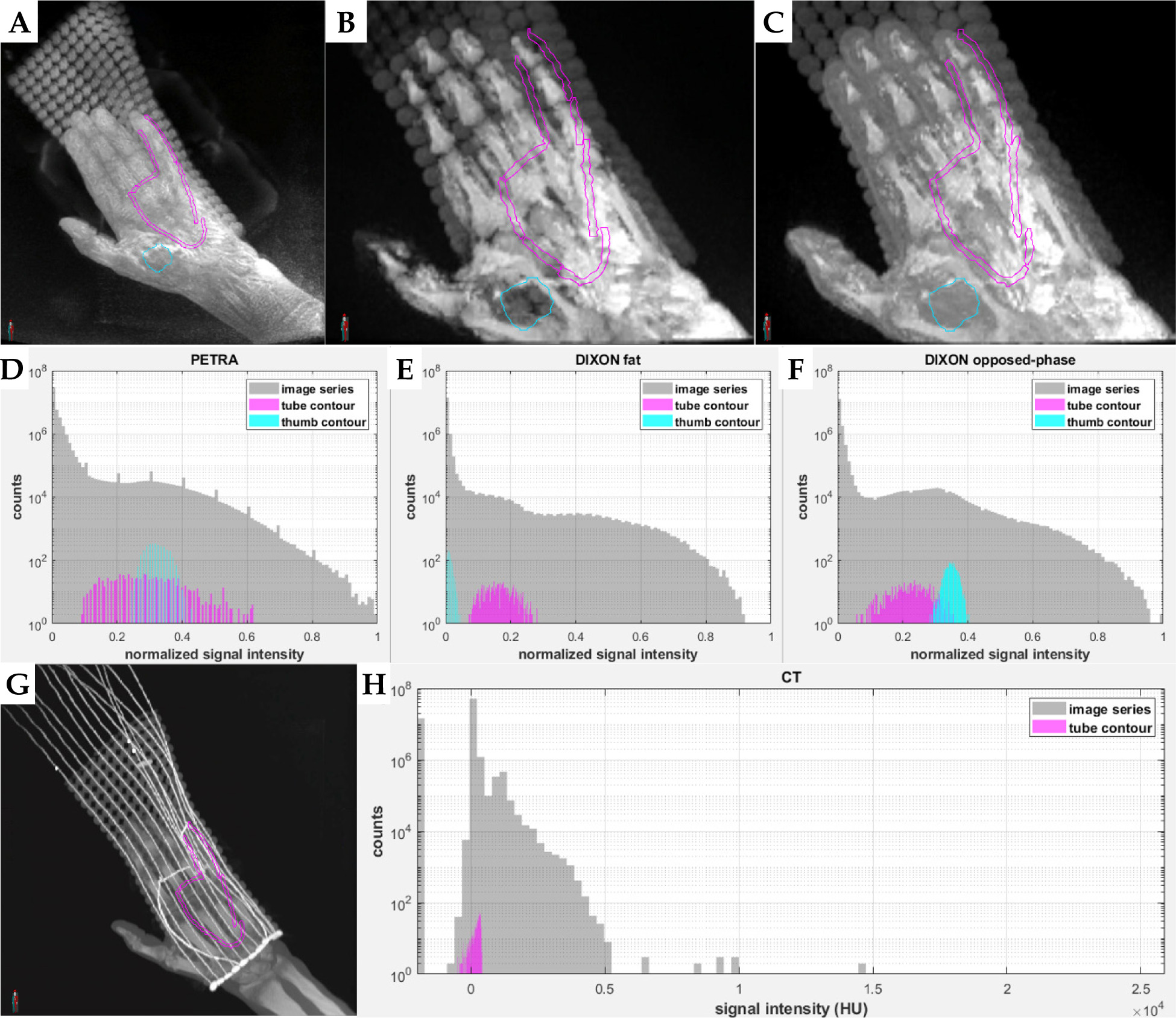
Signal intensity distributions of the 3 mm diameter silicon rubber tubing were symmetrical for the MR series, but negatively skewed for the CT series of both patients. Figure 9D-F displays histograms of normalized signal intensity for each MR series and for both MIM drawn contours of patient #3, along with the signal intensity histogram of CT series and of the tube contour for this patient (Figure 9H). The median, mean, and standard deviation of the mean signal on CT was 169 HU, 107 HU, and 232 HU for patient #2, and 258 HU, 194 HU, and 189 HU for patient #3. The median, mean, and standard deviation of the normalized signal intensity for the tube and thumb muscle contour on each MR series and patient are listed in Table 1. Ratios of median or mean tube over median or mean thumb signal intensity were similar between the two patients for the PETRA and Dixon OP series (around 0.9 and 0.7, respectively). On Dixon fat, the silicon rubber tube presented 13 to 19 times higher median or mean signal intensity than muscle tissue, with values close to zero. The larger variation of median and mean ratios between the two patients may have been caused by the low thumb tissue signal intensities on these images.
Table 1
Median, mean, and standard deviation (SD) of normalized signal intensity of the tube and of the thumb muscle contour for each MRI sequence acquired for two patients on whom the 3 mm diameter silicon rubber tubing was applied. The ratios of median tube signal/median thumb signal and mean tube signal/mean thumb signal are displayed in the two last columns for each sequence and patient
Discussion
This work evaluated silicone rubber tubes as alternative skin markers for MR-only surface HDR brachytherapy. The criteria for selecting these tubes were visibility on both MRI and CT, similarity to CT markers, flexibility, durability, non-toxicity, and low cost. Silicone rubber was presented as a suitable candidate, since it is the material comprising FF applicator beads, which generate positive signal on CT and on optimized VIBE and PETRA MR sequences used for brachytherapy treatment planning [13-15]. For all imaging sessions, the tested tubes produced comparable positive signal intensity as the FF applicator spheres within the same series, confirming the similarity of their materials. The employed MR sequences have short enough TR and TE to capture the magnetization relaxation of substances with relaxation times in the order of milliseconds, and were thus used to image the silicon rubber tubes. Although PETRA and VIBE are product sequences on Siemens scanners only, similar MR sequences allowing imaging of materials with such short relaxation times are available on other clinical scanners, increasing the adaptability of these tubes across different MR platforms. For example, ultra-short echo time (UTE) sequences may replace PETRA whereas “LAVA-Flex” or “mDixon” may replace Dixon VIBE on GE or Philips scanners, respectively, for silicon rubber visualization.
Solid tubing was selected to avoid signal loss and susceptibility of artifacts caused by air in hollow tubes. The employed silicone rubber tubing is flexible and adaptable to the shape of complex surfaces. It is non-toxic, easily obtained at low cost, can be disinfected with wipes, and can be cut to the required length with usual scissors. It was well-tolerated by human subjects and remained in place when applied on the skin with standard tape. However, this specific tubing was not originally intended for medical use, limiting its application on intact skin only. Nonetheless, the findings of this work about the suitability of silicon rubber as an MR and CT surface marker material may lead to the production of medical grade silicon rubber tube markers in the future.
The phantom and volunteer scans simulated the clinical setup for palmar fibromatosis treatments with surface HDR brachytherapy at our institution. Silicone rubber tubes of 2 mm diameter were initially procured to exactly match the diameter of CT employed skin markers. These tubes were detected in their entirety on the selected Dixon VIBE series by a brachytherapy TPS when used as surface markers on the phantom. However, they were not identified on all subsequent axial slices for the healthy volunteer and patients, resulting in fragmented tube contours. A possible reason for this discrepancy is that the phantom surface was harder and less pliable than human palms, into which the 2 mm diameter tubes partially sank when pressed by FF applicators fixed on the palms. Tube detectability was reduced when the tube was squeezed tightly on human skin by the applicator beads which produced comparable signal intensity.
The application of the 2 mm diameter tube on a palmar fibromatosis patient revealed that this alternative skin marker was visible on CT scans with similar signal intensity as the surface applicator beads. The shape of the partial tube contours produced using MR images generally agreed with the CT marker contour produced using CT images and the known positions of both markers during patient setup. Considering that 2 mm diameter tubing did not consistently provide sufficient MR signal for its identification, thicker tubes of 3 mm diameter were acquired and tested on the same phantom and volunteer. Except for their size difference, these tubes share similar characteristics as the 2 mm diameter tubes, and can be implemented clinically in the same way. As expected, the 3 mm diameter tubes produced a larger positive signal cross-section, and were therefore definitely detected on the axial Dixon and PETRA MR images of the phantom and volunteer, yielding complete contours on the TPS. Presumably, a smaller proportion of these thicker tubes was fully immersed into the skin, leaving a larger signal producing section outside the skin than the thinner 2 mm tubes. The thicker tubes did not impact FF applicator placement. The 3D sampling scheme of the VIBE sequence allowed for image acquisition in coronal orientation when necessary for covering the whole hand and applicator, while offering reliable reconstruction in the axial plane for tube detection.
The application of the 3 mm diameter silicon rubber tubing as a separate skin marker on the two last patients revealed that it was detected on CT images with the majority of its signal intensity values between –300 and +400 HU. The tube presented the largest contrast to muscle tissue (up to a factor of 19) on the Dixon fat, rather than on the Dixon OP and PETRA series, for which the normalized signal intensity of the tube and reference tissue partially overlapped. The visualization of silicone rubber tubing on the Dixon fat-only images agrees with expectations that the resonance frequency of silicone is closer to that of fat than of water [21]. A gap of 1-2 mm length was often observed between the tube and visible hand tissue on the Dixon fat images, presumably caused by the lack of adipocytes in the epidermis and dermis as well as their abundance in the lower hypodermis. Tube identification on human subjects was aided by its separation from the upper skin layers on the Dixon fat series, which depicted the hypodermis only. However, this MR series was less reliable for the anthropomorphic phantom, because the Dixon’s algorithm is optimized for human tissues on clinical MR scanners.
Despite low signal contrast between the 3 mm tubing and muscle tissue on the Dixon OP and PETRA patient images (~0.7 and 0.9, respectively), the tube could be distinguished from the skin surface owing to the darker surrounding air gaps. The “India ink artifact” [22] appearing as a dark band on the interface of tissues with different fat content on the Dixon OP images also helped with tube detection. Therefore, additional consideration of tube visibility on the original OP VIBE images may be helpful to confirm the presence of a silicone rubber tube on the reconstructed Dixon fat images, since water-fat separation may not always work properly. In general, it was more difficult to differentiate between the tube and skin on PETRA, which is known to offer low contrast between different tissues [23], than on the two Dixon VIBE series. Nonetheless, having multiple MR datasets can be advantageous for cross-referencing the tube presence, as suggested by the similarity of tube contours derived from them.
Oncentra Brachy TPS detected the 3 mm diameter tubing when employed as a surface marker in a clinical setting, to its full extent on CT images and partially on MR images. The standard TPS approach of using axial images only for skin marker detection resulted in less accurate tube contours than the custom approach of additionally consulting the sagittal and coronal views of the 3D MR acquisitions. Thus, treatment planning adaptation to reference the three orthogonal orientations during contouring can improve the visibility of silicon rubber tubing as surface marker on MRI. Moreover, careful consideration of auto-interpolation settings and contour revision is required to ensure faithful representation of individual tube segments.
Following our observations, we propose that 3 mm diameter silicone tubes can be used as surface markers for MR-only surface HDR brachytherapy. The visibility of these tubes is limited to MR sequences with very short TR and TE, but such sequences can be included in a protocol aiming to detect brachytherapy flap applicators. As demonstrated by our clinical application, tube detectability on both CT and optimized MR images may allow their use in conjunction with standard CT markers during a transition and testing phase, ultimately leading to replacement of current CT markers and MR-only HDR brachytherapy treatment planning. The geometric accuracy of silicon rubber tubing localization using MRI remains to be determined by future work. Developing methods for silicone-specific MR imaging would be helpful for clearer distinction of such tubes from the underlying skin.
Conclusions
Solid silicone rubber tubes of 2 and 3 mm diameter were detected on CT as well as PETRA and VIBE MR images of an anthropomorphic phantom and four human subjects using a brachytherapy TPS. The thicker 3 mm diameter tubes represent a suitable skin marker alternative to CT markers for target volume demarcation in MR-only surface HDR brachytherapy.


