
Purpose
A 5-year ipsilateral breast tumor recurrence (IBTR) in targeted intraoperative radiotherapy (TARGIT) arm was 3.3% in intra-operative radiotherapy (IORT) arm and 1.3% in whole breast irradiation (WBI) arm (p = 0.042). Overall recurrence risk was also higher in IORT arm, with hazard ratio (HR) = 1.44 and p = 0.053 [1]. At our institution, Axxent eBT system (Xoft) are used to treat early-stage breast cancer. An isotope-free miniature X-ray source is used to generate a 50 KV photon spectrum to deliver intra-operative radiotherapy (IORT) [2-4]. Patient is placed under general anesthesia to receive IORT immediately after breast-conserving surgery. An appropriately sized Axxent balloon applicator is implanted into the patient, based on its’ tumor cavity size and shape. A computed tomography image of the implanted balloon is used to develop eBT brachytherapy treatment plans. A single-dose of 20 Gy provided by Xoft X-ray radiation is delivered for patient’s treatment using a generator at the balloon surface [5]. Once IORT is delivered, the single-use disposable applicator is removed, and surgery can be completed.
Volume needed for treatment is calculated based on target area with a 10 mm thickness of the soft tissue surrounding different balloon sizes. Interface of the balloon with a wound bottom is appropriately sutured to avoid displacement and bursting during electronic brachytherapy dose delivery. The skin must be retracted from the applicator to minimize the dose delivered to the skin surface. At the same time, unacceptable delivery occurs if minimum distance from balloon surface to skin surface is less than 7 mm in early-stage breast cancer IORT [6]. The sterilized applicator is inserted by a surgeon and radiation oncologist in a correct position, with an entrance angle to direct electronic source through underlying tissues to the target. Surgeons and radiation oncologists must ensure that at least 1 cm of all breast tissue in the cavity covers the applicator, so that no part of the skin is positioned less than 1 cm away from the applicator. Because Asian female breasts tend to be thin and small, the dissected skin surface usually cannot meet the requirement of a 1 cm distance. The current study was performed in a phantom to simulate a situation, in which patient’s skin distance was less than 1 cm. A flexible magnetic material called ‘neodymium-iron boron’ (NdFeB + alloy-49) [7] was used to reduce breast skin radiation damage, especially when the gap between applicator surface and patient’s skin was less than 1 cm.
Breast-conserving therapy cannot benefit women living in developed countries and their remote areas because of travel distances between their homes and radiotherapy centers. In addition, they cannot stay or travel daily over such distances for the duration of one and half months of post-operative radiotherapy. As a result, they must choose mastectomy. These women could undergo breast-conserving therapy in one session with this novel approach.
Material and methods
A flexible water-cooling Xoft Axxent source (Xoft Inc., USA) catheter with a 25 mm length and 5.4 mm diameter was positioned inside an applicator for early-stage breast cancer treatment in this study. We adopted the AAPM TG43 report [8-11] for dose calculation and implemented this approach to all dosimetry parameters in BrachyVision™ treatment planning system (TPS) for Xoft Axxent source. A dose of 20 Gray (Gy) X-ray radiation was delivered from a generator to the balloon surface to a small very high-dose region close to the applicator, which attenuates quickly () from 20 Gy on the balloon surface to about 5 Gy at 1 cm from the balloon surface [12]. Xoft has three energy modes of 40, 45, and 50 KVp, and we double-checked our own office standard only for a well chamber calibration coefficient of 50 KVp; therefore, 50 KVp was used for this study only and in clinical practice.
This experimental design was motivated by small and thin breast sizes of Asian female patients, in which the skin surface usually cannot meet the 1 cm requirement during surgery. Therefore, a magnetic material of NdFeB + alloy-49 was used to repel photon-induced low-energy electrons for skin preservation to compensate for deficiency of tissue thickness, resulting in a gap of less than 1 cm between the applicator surface and the breast skin.
IORT technique and procedure – assessing balloon size
Since the patient’s skin dose is related to the balloon size, and the entire breast tissue in the cavity opposes the applicator at a distance of no less than 1 cm during IORT treatment, once our experiment’s results proved to be useful, the diameter of cavity had to be evaluated with a tool after tumor removal. The Xoft balloon shaft has a series of small ports on the distal and proximal sides of the balloon to remove small pockets of seroma or blood, which might accumulate around the balloon. Some factors may influence the study results theoretically when conducted in clinical practice, such as seroma, blood, and cavity distortion. To avoid a significant amount of blood oozing from capillaries during radiotherapy, hemostasis of the breast wound must be rechecked. A distortion could potentially occur owing to cavity formed around the applicator. At the same time, one must note that the dose delivered to target tissues can be changed due to the distortion caused by the cavity. The usual size of the applicator was 30, 40, or 50 cm3. A purse-string suture was used to conform the tissue and skin over the balloon in lumpectomy cavity during treatment. The dose to target tissues depended on how well the purse-string stitch was made. To avoid the skin being positioned less than 1 cm from the applicator, the stitch had to be made not within subcutaneous tissues, but deep into the whole cavity edges through the breast tissue. A major requirement should be followed when the balloon applicator is in place, so that the entire breast tissue in the cavity opposes the applicator at a distance of no less than 1 cm between the skin and the applicator [13].
Neodymium-iron boron (NdFeB) magnetic deflector and alloy-49 magnetism saturation material
For neodymium-iron boron (NdFeB), a permanent magnet of alloy-49 deflector with dimensions of 15 cm × 15 cm × 0.1 cm was used as a photon-induced electron contamination deflector. The weight was approximately 78.5 g for each of magnetic deflectors, with a 100 μm thick NdFeB alloy-49 coating on 1 mm thickness industrial flexible rubber. The surface with coated magnetic material (NdFeB), always faces the patient when used.
A magnetic saturation material called ‘alloy-49’ was applied, with a permeability of 1.05 to shift the magnetism at a distance of approximately 1 mm. NdFeB permanent alloy-49 magnet is a magnet with robust performance within contemporary magnets. Its main raw materials include metal ruthenium, pure iron, and boron-iron alloy. Alloy-49 conforms to spec ASTM A753 alloy type 2, MIL-N-14411 composition interface 3. This magnetic saturation material can shorten the magnetism at the interface of magnetic material and the skin. A Daley electronics Tesla meter (T-22A) was applied to measure strengths of magnetic field. The magnetic strength of neodymium-iron boron magnets + alloy-49 was 0.03-T each, which was approximately 100 of 3.0-T MRI, which was 105 times greater than the Earth’s magnetic field. Magnetic influence was evaluated, when NdFeB alloy-49 was near other common electronic devices, such as computer monitors and kilovolt generators [14].
Dosimetry of Xoft
Calibrations were performed by comparing well-type ionization chamber response to air kerma with a NIST primary X-ray standard, and dosimetry of Axxent low-energy X-rays was commissioned [15-17]. The dosimetry of superficial therapy and the dosimetry at the surface of a phantom were recommended [18].
Axxent system incorporates a commercially available well chamber and electrometer (Models HDR 1000 Plus and MAX-4000, respectively) supplied by Standard Imaging Inc. A custom insert, with higher attenuation than Standard Imaging Inc. also provided a typical insert, specifically for the Axxent system (Standard Imaging Inc., part number 70088).
Output calibration
The NIST (National Institute of Standards and Technology) and the University of Wisconsin ADCL (Accredited Dosimetry Calibration Laboratory) protocols were adopted for EB sources air-kerma calibration. Air-kerma strength was measured at 50 cm from the source surface, perpendicularly to the long axis. The detector positioning accuracy and the energy dependence of any solid water material were the main uncertainties in this study. TG-43 formalism was adopted to calculate absorbed dose to water. The absorbed dose of a reference point 1 cm from the source was specified using TG-43 report.
A calibration curve with GAF chromic film
GAF chromic film presented tissue equivalence (Zeff = 6.98), with a faster polymerization (image-forming) process (readout possible after 2-4 hours) of absorption peaks, which represented energy independent of the radiation. Increased sensitivity (useful dose range of approx. 0.02-0.8 Gy) and enhanced homogeneity (< 2% for exposed film) were suggested to be used for quality assurance and dosimetry in modern radiotherapy techniques.
An international protocol was adopted for film process and optical signal analysis of the low-energy radiation distribution [19]. GAF chromic EBT2 film (ISP Technology Inc., Wayne, NJ, USA; Lot # F05090901, expiry date April 2019) was used. Density irregularities, caused by uneven thickness of active layer by irradiating the films with a double irradiation technique were removed, which effectively reduced non-uniformity of GAF chromic film. A double exposure technique was adopted to deliver an initial dose of 2 Gy to each film on a linear accelerator before irradiation, and was applied to the film to achieve 2% of variation in dose uniformity [20]. Films were fabricated as 50 mm × 50 mm squares for advanced exposure prior to the study as a double exposure technique, and then were embedded into a solid water phantom at a depth of 5 cm. Because of layer separation extending up to 8 mm, a frame of 40 pixels (approx. 1 cm) from film edges was excluded from data collection. An 11 cm × 11 cm field size at SAD (source-to-axis distance) of 100 cm was conducted for radiation delivery with a photon energy of 6 MV of Elekta linear accelerator. A graded dose from 0.1 Gy to 0.2 Gy in a step size of 0.1 Gy was applied for calibration curve measurements.
Phantom measurements of photon-induced electrons repulsed by NdFeB + alloy-49 in a linear accelerator
The magnetic deflection power was assessed with Elekta Synergy 6-MV photon beam at 11 cm × 11 cm, by placing the chambers or GAF chromic film in a solid water phantom, as shown in Figure 1.
Fig. 1
Experimental setup of photon-induced electron repulsion phantom measurements using NdFeB + alloy-49 under 6-MV high-energy photon beam linear accelerator. The NdFeB side was facing parallel plate ionization chamber for exit dose electron contamination repulsion measurement. Conversely, the rubber side of magnetic material facing plate ionization chamber has no function in reducing electron contamination
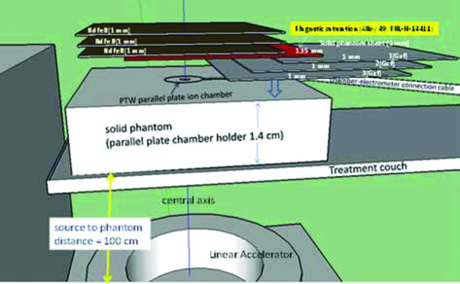
A PTW Markus parallel plate ionization chamber in a solid water stack phantom with a thickness of 1.4 cm was used to measure magnetic repulsion of the photon-induced electron contamination in a high-energy medical linear accelerator [21]. A PTW Unidose model 30010 electrometer at 300 V of bias voltage was connected through a triaxial cable to chambers. The influence of various NdFeB layers + alloy-49 in various solid phantom sheets was measured to obtain exit dose build-up curves on the central axis for open field to estimate optimal electron contamination repulsion. The magnetic electron deflector was made with a thickness of 1 mm of NdFeB attached by a 1 mm thick rubber. NdFeB side faced a parallel plate ionization chamber for electron contamination repulsion measurement, while facing the rubber side to the parallel plate ionization chamber did not reduce electronic contamination. A magnetic saturation material alloy-49 was placed in front of NdFeB to shift the magnetism on the interface of magnetic material and the skin, as shown in Figure 1. Electron contamination repulsion rate was defined by a ratio of reading with NdFeB side + alloy-49 facing parallel plate ionization chamber to that of a p-p chamber reading without any magnetic material. All the measurements were repeated 5 times to ensure that the deviation of electrometer readings gathered from the ion chamber was less than 0.5%. All the data were calculated or measured for population standard deviation and sample standard deviation. The overall population standard deviation was 0.048%, and the sample standard deviation was 0.051%. The standard errors of mean and 95% confidence interval were 0.016% and 0.031%, respectively.
GAF chromic film was placed at positions 1, 2, and 3 (as shown in Figure 1), or with more thickness in a solid water phantom to compare the exit dose curves acquired by a parallel plate chamber to examine electron contamination repulsion ability.
Film processing
Epson Expression 10000XL scanner was used for the film scanning in 48-bit RGB mode, and the data were saved in a tagged image file format (TIFF). To obtain an H-D calibration curve, the optic density to dose conversion was analyzed using VariSoft for imaging processing. To reduce the variation in OD to within 2%, the films were scanned in a landscape orientation [22]. To reduce temperature-dependent effects, the experiments and film processing were conducted at room temperature [23]. All optical density conversions were performed within one day after irradiation to avoid time effects during the measurements. Forceps were used to manage GAF chromic film to minimize scratching and fingerprints. OD, net optical density was determined using the following equation:
OD = log10 (I0/I),
where I0 was the background (i.e., the scanner signal for an unexposed film), and I was the scanner signal for the exposed film.
Red filter
The net optical density resulted in an H-D curve as a function of radiation exposure or dose. To increase the gradient of the H-D curve, a red filter was placed on GAF films to increase the resolution of dose-OD response curves [24] during film scanning. By subtracting the reading for base signal from the measured optical density and to obtain the net optical density, the quantity of radiation dose was derived.
Photon-induced electrons repulsed by NdFeB + alloy-49 in Xoft
Three sets of different cavity volumes of 30, 40, and 50 cm3 solid water phantoms were made to simulate the balloons inside breast-conserving surgery cavities, and to measure the repulsion of photon-induced electrons by NdFeB + alloy-49 in Xoft (Figure 2).
Fig. 2
A sheet of GAF chromatic film was placed adjacently to the phantom surface and kept in place with transparent tape on the breast phantom, with the catheter at an angle of 45° oblique to the surface, to measure the skin dose in a single-dose IORT. A set of radio-chromatic film (RCF) were placed adjacent to the skin surface and fix in place without movement with tapes in order to measure the skin dose
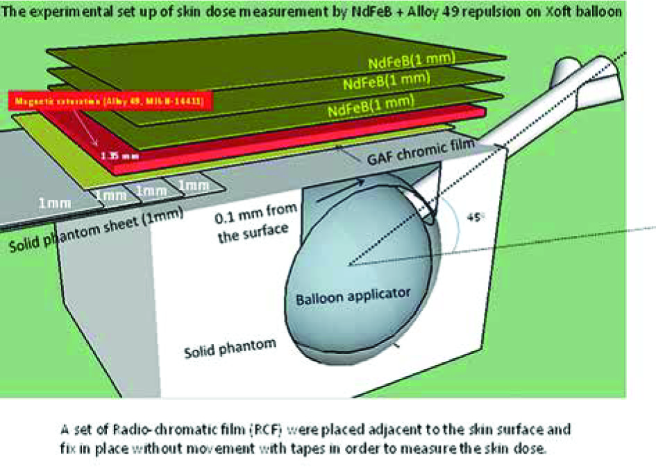
The balloon was placed at three different orientations of catheters to the surface angle for surface dose measurement. The constructed design of the balloon cavity surface-to-phantom surface distance was 0.1 mm, and a phantom skin-like bridge could be created by adding the solid water phantom, 1 mm by 1 mm, to any desired thickness. Skin dose measurement was performed with a stationary dwell position located at the balloon isocenter, providing the predicted dose of 5 Gy at 1 cm from the balloon surface. The prescribed dose was assigned to the skin surface if the distance between the balloon surface and the skin surface was less than 10 mm. Measurements were also performed when the minimum distance from the balloon surface to the skin surface was less than 10 mm. Considering the patient load tolerance of magnetic materials and the efficiency of repulsion of electronic contamination, only three layers of NdFeB + alloy-49 sheets were placed on the phantom surface to simulate clinical situation. GAF chromic film was then embedded between the NdFeB sheet bottom and the top of solid water phantom layers for the skin dose measurement. The repulsion rate of electron contamination was defined by the ratio of dose converted by a GAF film on the phantom surface-air interface to that of NdFeB side-facing GAF film.
Balloon insertion orientations to optimize skin surface dose delivery
According to the operation procedure, the balloon insertion orientations to optimize skin surface dose delivery were also evaluated. Small distance between the balloon and the skin surface could result in a skin dose escalation. The symptom of telangiectasia is believed to be associated with late skin toxicity if the distance from the balloon to the skin is short. Anisotropy, with constriction of isodose distribution at the proximal end of the catheter is beneficial for preventing skin damage caused by electronic brachytherapy using balloon applicators. Such anisotropy can be considered an advantage in reducing skin dose, when the distance between the cavity and the skin is small. In this study, an optimization of the skin surface dose was simulated with various balloon-insertion orientations using home-made breast phantoms. Three different catheters, perpendicular to the surface, oblique to the surface at an angle of 45°, and parallel to the surface, were placed on surface orientations for the geometry-driven dose optimization analysis.
Film exposure orientation by Axxent Xoft
Radiation doses of 2 Gy were applied to GAF film in advance using an Elekta linear accelerator as previously described for dose uniformity in calibration curve measurements. 11 cm × 11 cm square films were then embedded between the NdFeB sheet bottom and the top of polystyrene layers to simulate a clinical setup for skin dose measurement. The catheter was placed at three different surface orientations, including perpendicular to the surface, oblique to the surface at 45°, and parallel to the surface. Then, Nucletron Plato treatment planning system (Nucletron, Columbia, MD, USA) was used for three-dimensional dose distributions. The dose was optimized to target volume with different thicknesses of polystyrenes on the balloon surface by selecting multiple dwell positions at three different catheter-surface angles. A volume from the balloon surface to a 1.0 cm distance from the phantom surface was defined as the target volume. The results of film exposure with NdFeB were compared with those of film exposure without magnetic materials to evaluate the reduction in skin dose.
Results
Photon-induced electrons repulsion with NdFeB + alloy-49 using linear accelerator
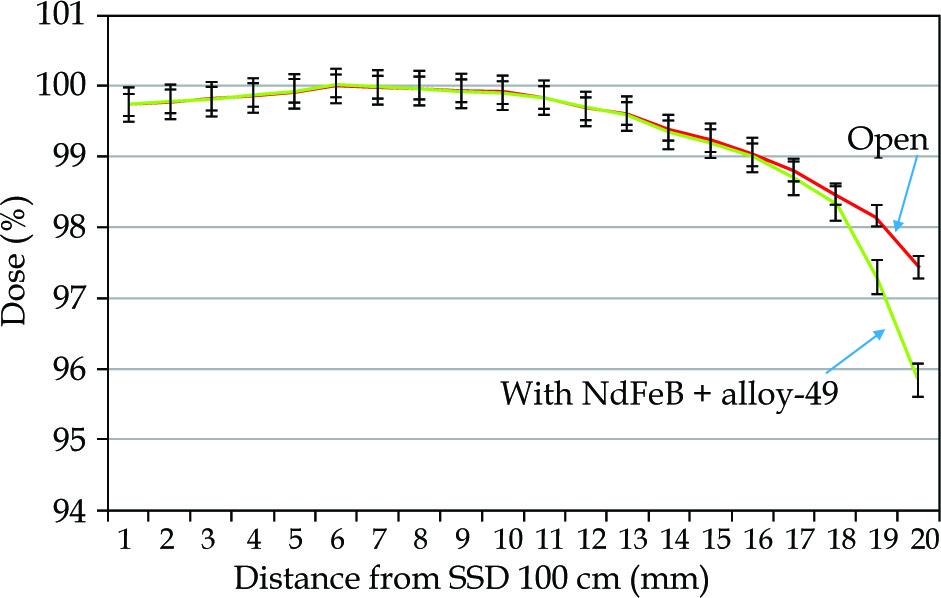
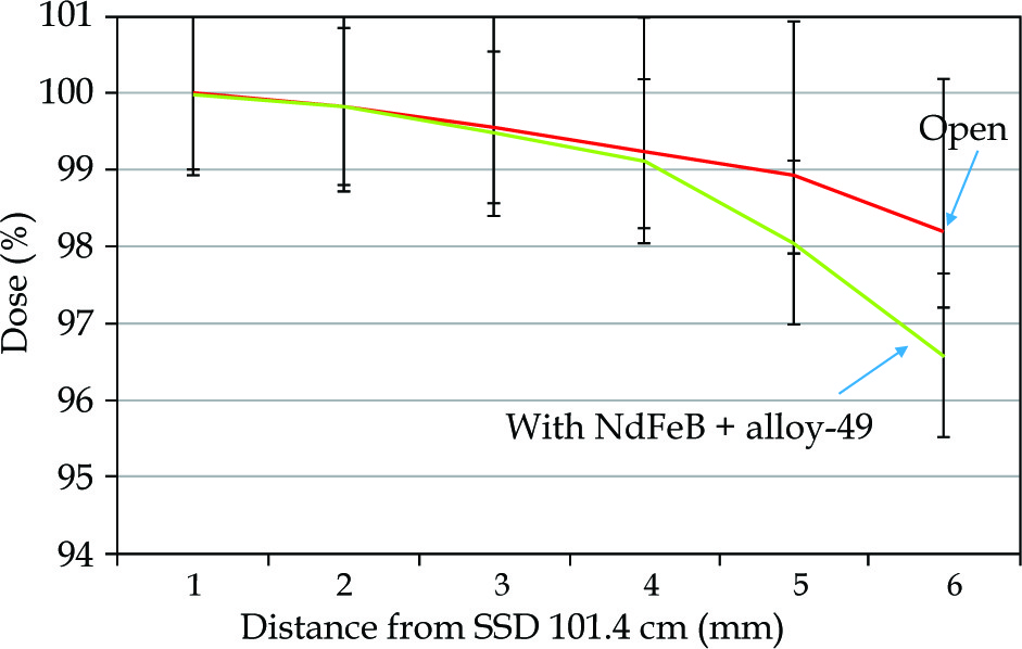
The skin exit dose reductions achievable with the introduction of magnetic deflector under a 6-MV high-energy photon beam, measured by GAF chromic film and parallel plate ion chamber are presented in Figure 3 and Figure 4, where a 2% within 2 mm of electrons repulsed at exit dose in this measurement is also shown.
Film calibration curve
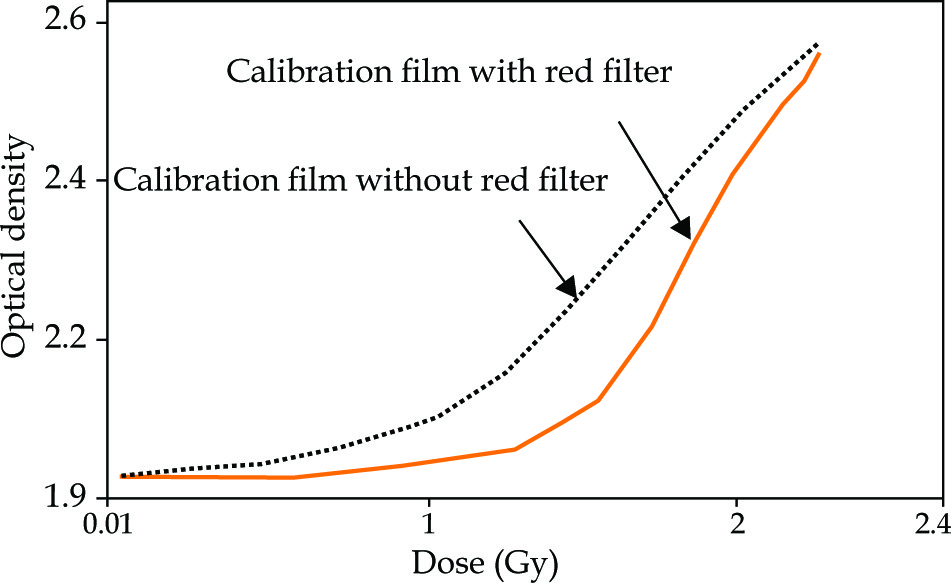
The calibration curve was sensitive and therefore steeper when the film was scanned using a red color filter (Figure 5). The dose of radiation was then derived from a densitometer OD.
Fig. 5
Calibration curve was steeper when scanned with a red color filter, and radiation dose was then derived from the measured optical density on the film
The results of chamber measurement were compared with films since the film was considered as a standard with higher resolution in relative dose measurements.
Skin surface dose according to balloon-insertion orientations
Varied sizes and shapes of balloon applicators resulted in different radiation dose ratios between tissues at the surface and the prescription dose. The reduction in dose delivery when using NdFeB with an applicator-skin distance from 1 to 10 mm, ranged from –2.44% to –5.73%, and –4.71% to –7.51% for balloon volume from 30 to 50 cm3, respectively (Table 1B). It was obvious that the magnetic repulsion was more effective when a large balloon was used at any depth between the balloon and phantom surfaces.
Table 1
Skin point dose repulsion from dose prescription of 5 Gy pointed 10 mm from the balloon surface with NdFeB + alloy-49 on balloon proximal point with 45° balloon-insertion orientations in three different balloon sizes
a Thickness as the distance from the dose prescription point at 10 mm from the balloon surface (for example, 10 mm thickness indicates that the distance is 20 mm from the balloon surface) with the balloon-phantom surface angle at 45°; The overall population standard deviation is 0.048%; The sample standard deviation is 0.051%; The standard error of mean and 95% confidence interval are 0.016% and 0.031%, respectively
The comparisons of skin doses were obtained in readings with and without NdFeB + alloy-49 at the surface point. A measured dose of 81% was the lowest surface dose for the perpendicular orientation compared to the predicted dose at a 1 cm distance from the balloon surface. The parallel orientation had the highest surface dose of 135%, while the oblique orientation showed intermediate results with a surface dose of 98%, compared to the predicted dose of 1 cm from the balloon surface. Tables 1A and 1B show only the skin surface dose repulsion with NdFeB + alloy-49 at 45° balloon-insertion orientations in three different balloon sizes. To simulate a clinical situation, the measurement of skin dose at every thickness was conducted. Thicknesses showed in Tables 1A and 1B are the distances from the dose predicted point on the balloon surface (for example, 10 mm thickness means that the distance was 10 mm from the balloon surface). The reduction using NdFeB at an applicator-skin distance of 10 mm (10 mm thickness in Table 1B), ranged from –5.73% to –7.51% for balloon sizes of 30 cm3 to 50 cm3, and only –1.77% to –3.55% at an applicator-skin distance of 0 mm (0 mm thickness in Table 1B) for balloons with volumes from 30 to 50 cm3. The skin dose reduction was at a maximum when the distance was 10 mm from the 50 cm3 balloon surface.
Table 2 describes skin dose repulsion at less than predicted 5 Gy point at a certain distance from the balloon surface with NdFeB + alloy-45 on the balloon proximal point, with 45° balloon-insertion orientations for three different balloon sizes. The reduction using NdFeB + alloy-49 at an applicator-skin distance of less than 10 mm, ranged from –4.93% to –6.91% for balloon volumes from 30 to 50 cm3, respectively.
Table 2
Skin dose repulsion at less than the dose prescription at a 5 Gy point, with a certain distance from the balloon surface using NdFeB + alloy-49 on the balloon proximal point, with 45° balloon-insertion orientations for balloons of three different sizes
a Thickness: the distance of the dose prescription point at a certain distance (mm) from the balloon surface with a balloon-phantom surface angle at 45°; btreatment plan prescription dose: the point of dose prescription is the thickness from the balloon surface; cactual measured dose; dSkin dose repulsion with NdFeB + alloy-49
Discussion
Scatter electron energy induced by a 50-kV photon beam can be compared with an interaction of high-energy photon with orbital electron. If the incident photon has very high energy that is much greater than the resting energy of electron, the photon drops most of its energy to Compton electron, therefore, the scattered photon has much lower energy. Thus, maximum scattered electron energy induced by 6-MV high-energy photon beam is approximately 0.25 MeV. The average photon energy of 50 KVp produced by Axxent eBT used in the current study was about 17 KeV. According to Compton scattering equation, the maximum scatter electron energy from a 50-KeV photon was 1.1 KeV when photon scattered at an angle of θ = 180°, and the maximum range in water (soft tissue) of electron energy 1.1 KeV was 0.0055 mm. In the present study, the electron induced by 50 KVp photon in Axxent eBT could be neglected or repulsed by neodymium-iron boron (NdFeB) + alloy-49. We learned that the skin dose was the sum of initial kinetic energies of all the charged ionizing particles (electrons and positrons) released by the uncharged particles (photons) in the basal and dermal layers [25].
The deflection and removal of high-energy electrons produced by a medical linear accelerator was attained by a neodymium-iron boron (NdFeB)+ alloy-49 permanent magnetic deflector device, in which photon-induced low-energy electrons are removed by magnetism. Low-energy photon exits the skin surface and penetrates through magnetic material without contributing any backscatter dose to the skin. Therefore, removal of electron contamination from a 50-kV electronic brachytherapy machine was achieved using NdFeB magnetic materials + alloy-49 magnetic saturation materials in this study.
To maintain optimal tumor cavity coverage and to minimize skin dose, the optimized Xoft Axxent balloon catheter and multiple dwell positions were used when the cavity-to-skin distance was small.
A lead-rubber protection sheet of 0.25 mm Pb equivalent is usually applied to cover the patient over the applicator in breast IORT treatments for radiation safety considerations [26, 27]. NdFeB + alloy-49 magnetic material can be used for EO sterilization only to avoid damage of volatile toxicity compounds. NdFeB + alloy-49 and other parts of the devices were ethylene oxide-sterilized before use. The skin above the breast of IORT lesion was wrapped with a sterilized plastic film before applying magnetic material to the patient skin surface. Using three stacked NdFeB + alloy-49 layers to repulse photon-induced electrons, not only provides skin preservation but also protects the patient during radiation treatment.
This system is contraindicated for implanting a balloon applicator if the size of resected tumor cavity is not consistent with inflated volume range, and general shape of a specific balloon is selected. A patient is not considered a candidate for radiation therapy with Axxent electronic brachytherapy system, if a minimum distance from the balloon surface to the skin surface is less than 7 mm. In certain conditions, for example, in patients with extreme or unusual anatomical features, such as extreme rib curvature or very irregularly-shaped lumpectomy cavities, the balloon applicator could become asymmetrically located, affecting conformal delivery of the radiation dose to the target tissue.
Conclusions
A magnetic material was used in a single-dose IORT to reduce breast skin radiation damage when the gap between the applicator surface and the patient’s skin was either more or less than 1 cm. The skin dose reduction using NdFeB at a certain applicator-skin distance could range from a minimum of –2.44% to a maximum of –7.51% for balloon sizes of 30 cm3 to 50 cm3. We noted that, in case of Asian patients, female breast shapes and sizes tend to be thin and small; therefore, the skin envelope usually could not meet the 1 cm requirement. Due to cosmesis and skin sparing required, we recommend that patients use magnetic material to repulse electrons for skin preservation during conservative early-stage breast cancer intra-operative radiotherapy.


